D. ATTACHING |
| THE |
| BAR | AND |
| CHAIN |
|
|
|
|
|
|
| WARNING! |
|
| / |
| !' | ||||||||||
|
|
|
|
|
|
|
|
|
|
|
|
|
|
| Never try to install the bar upside down to avoid in- | |||||||||||||||
_ICAUTION:!Wear | protective | gloves | when | han. | creasing the hazard of kickback. |
|
|
|
|
|
| |||||||||||||||||||
dling or operating your saw. The chain is sharp | c. Hold chain with cutters facing as shown in | |||||||||||||||||||||||||||||
and can cut you even when it isnot moving! |
| |||||||||||||||||||||||||||||
|
| Figure | 6. |
|
|
|
|
|
|
|
|
|
| |||||||||||||||||
• | Your saw | is equipped | with | a |
| Guide |
|
|
|
|
|
|
|
|
|
|
| |||||||||||||
| d. Place | chain | over | and | behind | the | clutch | |||||||||||||||||||||||
| Bar and a Guard | Link Chain designed | to help |
| drum |
| onto | the | sprocket, |
|
|
|
|
| ||||||||||||||||
| reduce | kickback. |
|
|
|
|
|
|
|
|
|
| e. Slide |
| Guide | Bar to the | rear of the | saw | as far | |||||||||||
• | Always | use the | Guide | Bar and | the |
| as possible. |
|
|
|
|
|
|
|
|
| ||||||||||||||
| Guard | Link | Chain | specified | for | your | chain | f, | Fit | the | bottom | of | the | drive | links | between | ||||||||||||||
| saw model, | when replacing | these | parts. |
|
| the | teeth | in the sprocket. |
|
|
|
|
| ||||||||||||||||
|
|
|
|
|
|
|
|
|
|
|
|
|
|
| g. Start at the top of | the bar and fit the chain | ||||||||||||||
|
|
|
| WARNING_ |
| - |
|
|
|
|
|
| drive | links | into | the | groove | around | the Guide | |||||||||||
|
|
|
|
|
|
|
|
|
|
|
|
|
|
| Bar. | Figure | 6. |
|
|
|
|
| ' |
|
| |||||
Do not start | engine without | guide | bar and chain | I | h. Pull | the | Guide | Bar forward | until | the chain is | ||||||||||||||||||||
completely | assembled. | Otherwise | the | clutch | I |
| snug |
| in | the | guide | bar | groove | Figure | 7. | |||||||||||||||
can come off and serious | personal injury could | / | i | Install | the outer guide | plate | "Figure3 | |||||||||||||||||||||||
..................................result: | : |
|
|
| : |
|
|
|
|
| J |
|
|
|
|
|
|
|
|
|
| by.__J_di_Lng....t.h'ebar | ||||||||
|
|
|
|
|
|
|
|
|
|
|
|
|
|
|
| clamp over the mounting studs arid fitting | ||||||||||||||
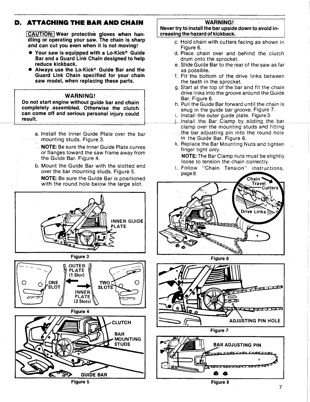
| a. Install | the | Inner:Guide | Plate | over | the | bar |
| .the |
| baradjusting | pin | into | the | round.hole | |||||||||||||||
....... | mounting | studs. | Figure | 3, |
|
|
|
|
|
|
| in | the | Guide | Bar. | Figure | 8. |
|
|
|
| |||||||||
| NOTE: Be sure the Inner Guide Plate curves | k. Replace the Bar Mounting Nuts and tighten | ||||||||||||||||||||||||||||
|
| finger | tight | only. |
|
|
|
|
|
|
| |||||||||||||||||||
| or flanges toward the saw frame away from |
|
|
|
|
|
|
|
| |||||||||||||||||||||
|
| NOTE: The Bar Clamp nuts must be slightly | ||||||||||||||||||||||||||||
| the Guide Bar. Figure 4. |
|
|
|
|
|
|
| ||||||||||||||||||||||
|
|
|
|
|
|
|
| loose to tension the chain correctly, |
| |||||||||||||||||||||
| b. Mount the Guide Bar with the slotted end |
|
| |||||||||||||||||||||||||||
| I, | Follow |
| "Chain | Tension, |
| •instructions, | |||||||||||||||||||||||
|
|
|
|
|
|
|
|
|
|
|
|
|
|
|
|
| ||||||||||||||
over the | bar mounting | studs. | Figure | 5. | page 8. | |
NOTE: Be sure the Guide Bar | is positioned | |||||
| ||||||
with the | round hole | below the large | slot. |
| ||
INNER GUIDE
PLATE
Figure 3 | Figure 6 |
|
Figure 4
c u'c"1
ADJUSTING PIN HOLE
Figure 7
BAR ADJUSTING PIN
6 6
Figure 5 | Figure 8 |
7