Owners Manual
SEARS, Roebuck and CO., Hoffman ESTATES, IL
IL Slope OPERA1ON
Customer Responsibilities
Maintenance Agreement
Product Specifications
SEARS, Roebuck and CO., D/817WA, Hoffman ESTATES, IL
Table of Contents
Performance
Engine Customer Maintenance
Ccessories and Attachments
Spark Plug Muffler
Contents of Hardware Pack
Assembl Y
Tools Required for Assembly
To Install Steering Wheel
Unpack Carton
Prepare Battery
Assembly
HOW to SET UP Your Tractor
Proceed to Activate the Battery
Poison Causes Severe Burns
To Install Mower Deck
Check Tire Pressure
Treatment
Belts
Reinstall Charged Battery
To Adjust Mower Deck Wheels
Check for Proper Position of ALL
Cause a spark
Inset
Check Starting Sequence Indicator Indicator lights if
Know Your Tractor
Tractor
To SET Parking Brake
HOW to USE Your Tractor
Operation
To USE Choke Control
To Operate Mower
To Select Mower Cutting Height
To Operate on Hills
To Transport Tractor
ADD Gasoline
ALL-WHEEL Steering Feature
Check Engine OIL Level
To Start Engine
Mulching Mowing Tips
When Mulching Lawn for the First T1ME
Mowing Tips
Retraining Lawn to be Cutwith Mulching Mower
Before Each USE
Fill in Service Dates AS YOU Complete Regular Service
Service Dates
Customer Responsibilities Schedule
Steeringgear
Lubrication Chart
Orientation view only,, Do Not stand on end
SAE 30 or 10W30 Motor OIL API SG @ General Purpose Grease
Blade Care
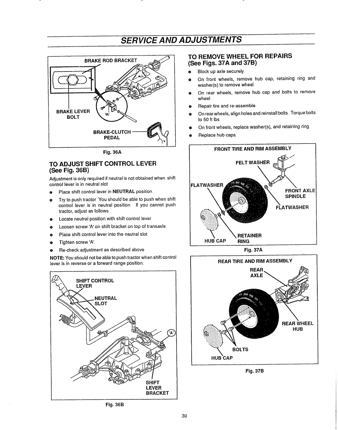
Service or Adjustments
Customer Responsibilities
Brake Operation
To Remove Mulching Plug
Keep battery and terminals clean
To Clean Battery and Terminals
See FIG
Lubrication
Engine
Recommended Viscosity Grades
AIR Screen See Fig
AIR Filter See Fig
Cleaning
Muffler
Spark Plugs
To Install Mower Deck
Tractor To Remove Mower Deck
Mowerdeck Hitch
Fig,.26A
Service and Adjustments
To Level Mower Deck
Engagementcable Mowerdeck
To Adjust Mower Deck Height See Fig
Qroove
To Adjust Blade Drive Belt
Service
Adjustments
Blade Brake Adjustment
Fig+29
To Adjust Tractor Drive Belt
To Replace Mower Blade Drive Belt
Fig, 30A
To Adjust Seat
To Replace Tractor Drive Belt
See Figs
To Adjust Brake ROD See a
To Adjust Tractor Brake
To Adjust Steering Gear
See Figs a & 34B
Lever
Bracket
Figo37A
To Replace Fuse See Fig
Battery See Fig
To Start Engine with a Weak
To Replace Headlight Bulb
Tanyard to Front
To Adjust Choke Control
To Remove Hood See Figs
Failing
To Adjust
Throttle CONTROl. Adjustment
Carburetor Adjustments
Initial Adjustment
Problem
Batterywill not charge
Poorcut-uneven
Engine
Battery
Storage
Engine OIL
Page
ALL Unnumbered
Craftsman 43 Lawn Tractor Model Chassis & Hood Assembly
USE Original
Items are Interchangeable
Description Qty
Craftsman 43 Lawn Tractor Model
314799 310006
Items
ALL Unnumbered Items are Interchangeable With Opposite Side
Hood and Chassis Assembly
Motion Drive
OKEY#t
Craftsman 43 Lawn Tractor Model
Qty
Reghexctrlk
Mower Suspension Assembly
Craftsman 43 Lawn Tractor Model 536.2558/0
322997F
180079
Standard Hardware
Lift J Black
Front Steering Assembly
Craftsian 43 Lawn Tractor 2,ODEL
Zerk Fitting
Standard Hardware Items
Rear Steering Assembly
326t37A
Tractor Model
Craftsman
Lawn
ROD. TIE
Items are Interchangeable
303109
Lawn Tractor Model
536.255870
3t2
Motion Drive Assembly
Craftsma 43 Lawn Tractor Model
328041A
Craftsman 43 t.AWN Tractor Model 536,255870
WASHER, Flat
Engine & Control Assembly
SCREW, 5116-18X .75HH C
QTY
305550 305552
CAP, Pipe 3/8918 NPT
PRE-PAINTED Deck Assembly
327957C
KEY#
PART# Description
Craftsman 43 Lawn Tractor Model Final Deck Assembly
Craftsman 43 t.AWN Tractor Model
Order Individual Parts Standard Hardware Parts
Electrical Assembly
Allunnumbered Items Areinterchangeable With Oppositeside
63 HHC
Steeringmower Wheeldeck
ALL Unnumbered
Items are Interchangable
320864 320865 322898
322909 328483
Shift Revineutral
Craftsman 43 Lawn Tractor Model Customer Assembly
Parts BAG Assy QTY1
Tire Size
Label
Engine Model 402707-1235-01 for 43 Tractor Model
556
881
OlOo,£
634A
552A 819 615 616 H @
020O,S
Gasketset
Pump Repair KIT
284
467467
601 535 235 643 445
Assembiles include all parts shown In frames+
523 265 267 209
229
209A 592 284A 201 525 524 C 207
803 311 1003 310 544
Engine Model 402707-1235-01 for 43 Tractor Model 783
513
Gro,up
334
482
851
332
573
Engine Model 402707-1235-01 for 43 Tractor Model 304
567
S73
Transaxle Repair Parts
Peerless Transaxle Model 930-045 for 43 Tractor Model
Key No, Part No. Description
Peerless Transaxle Model 930-045 for 43 Tractor Model
Key
This Transaxles Capacity is 24 OZ
03/12/93
Part Number