MAINTENANCE AND TROUBLESHOOTING
Inspect and properly tighten all parts of the exercise cycle regularly. Replace any worn parts immediately.
To clean the exercise cycle, use a damp cloth and a small amount of mild
important: To avoid damage to the console, keep liquids away from the console and keep the con- sole out of direct sunlight.
PULSE SENSOR TROUBLESHOOTING
For optimal performance of the pulse sensor, keep the metal contacts clean. Clean the contacts with a soft
Avoid moving your hands or squeezing the metal con- tacts too tightly while using the pulse sensor; doing so may interfere with heart rate readings. For the most accurate heart rate reading, hold the metal contacts for about 15 seconds.
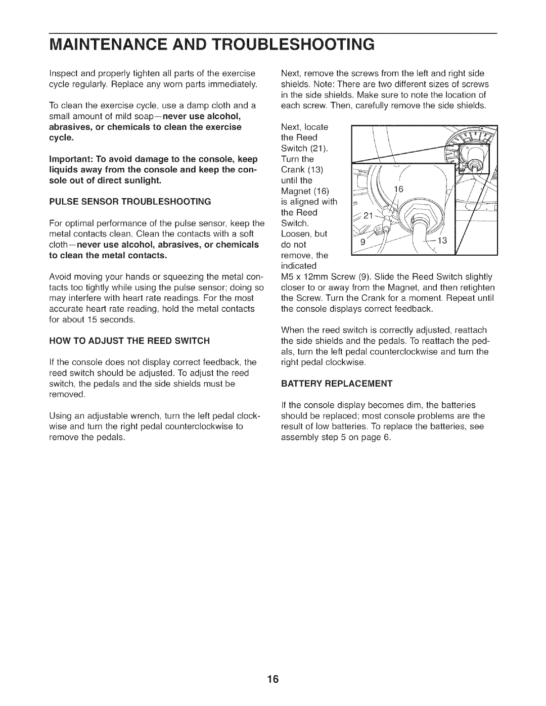
HOW TO ADJUST THE REED SWITCH
If the console does not display correct feedback, the reed switch should be adjusted. To adjust the reed switch, the pedals and the side shields must be removed.
Using an adjustable wrench, turn the left pedal clock- wise and turn the right pedal counterclockwise to remove the pedals.
Next, remove the screws from the left and right side shields. Note: There are two different sizes of screws in the side shields. Make sure to note the location of each screw. Then, carefully remove the side shields.
Next, locate the Reed Switch (21). Turn the Crank (13) until the
Magnet (16)16 is aligned with
the Reed Switch. Loosen, but do not remove, the indicated
M5 x 12mm Screw (9). Slide the Reed Switch slightly closer to or away from the Magnet, and then retighten the Screw. Turn the Crank for a moment. Repeat until the console displays correct feedback.
When the reed switch is correctly adjusted, reattach the side shields and the pedals. To reattach the ped- als, turn the left pedal counterclockwise and turn the right pedal clockwise.
BATTERY REPLACEMENT
If the console display becomes dim, the batteries should be replaced; most console problems are the result of low batteries. To replace the batteries, see assembly step 5 on page 6.
16