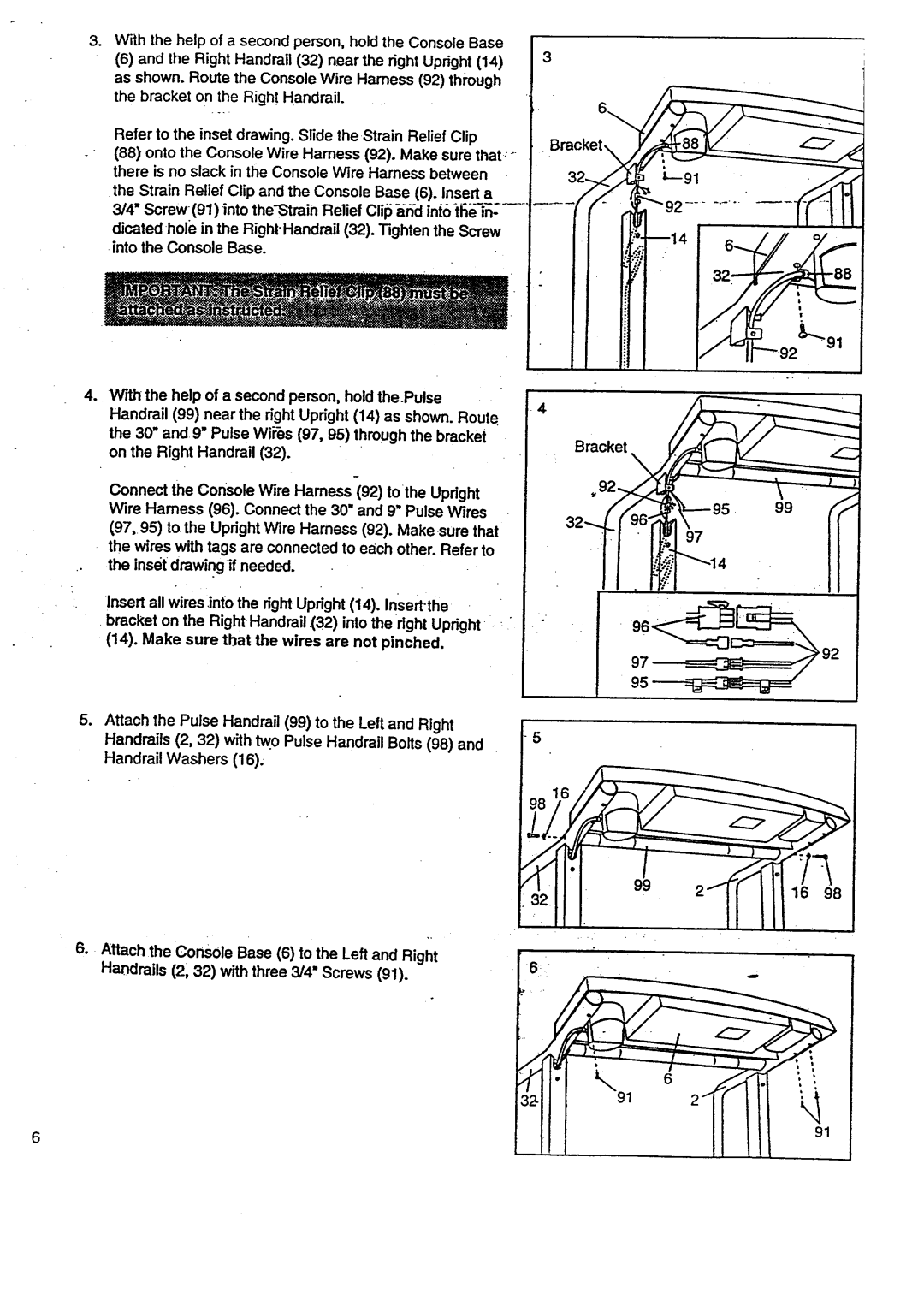
. With the help of a second person, hold the Console Base
(6)and the Right Handrail (32) near the right Upright (14) as shown. Route the Console Wire Hamess (92) through the bracket on the Right Handrail.
Refer to the inset drawing. Slide the Strain Relief Clip
(88)onto the Console Wire Harness (92). Make sure that; there is no slack in the Console Wire Harness between the Strain Relief Clip and the Console Base (6). Insert a 3/4" ,Screw (91) into
dicated hole in the Right.Handrail (32). Tighten the Screw into the Console Base.
oWith the help of a second person, hold the.Pulse Handrail (99) near the right Upright (14) as shown. Route the 30" and 9" Pulse Wii'_s(97, 95) through the bracket on the Right Handrail (32).
Connect the Console Wire Hamess (92) tothe Upright Wire Hamess (96). Connect the 30" and 9" Pulse Wires
(97,95) to the Upright Wire Harness (92). Makesure that the wires with tags are connected to each other. Refer to
.° the inset drawing if needed.
Insert all wires into the right Upright (14). Insertlhe bracket on the Right Handrail (32) into the right Upright (14). Make sure that the wires are not pinched.
Bracket_
__.92_"91
4
Bracket
99
4"
5.Attach the Pulse Handra_ (99) to the Left and Right Handrails (2, 32) with tw.o Pulse Handrail Bolts (98) and
Handrail Washers (16).
5
98
=/
32 1 - ll III,°°°
6.Attach the ConsOle Base (6) to the Left and Right
Handrails (2, 32) with three 3/4" Screws (91).
| 6 |
| 91 |
6 | 91 |
|