SMC sierra monitor corporation

Sentry Instruction Manual - Version 6

The SENSOR FAILURE message for toxic gas sensors does not indicate a specific failure of the sensor but indicates that the sensor is not correctly connected to the electronics. If this message appears check that the sensor harness is correctly installed to the connector on the bottom electronics board.

The gas sensor which is located inside the sensor assembly housing can be replaced without replacement of the housing. To replace the sensor:

1.Confirm that system power has been removed.

2.Remove the transmitter electronics board from the main housing and unplug the sensor harness from the transmitter electronics.

3.Unscrew the sensor housing from the bottom of the enclosure

4.Hold the sensor assembly so that the harness faces down and the sensor faces


up. Unscrew and remove the round


section

of

the

housing

from

the

hex


section. Be careful not to lose the spacer


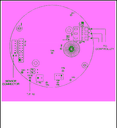
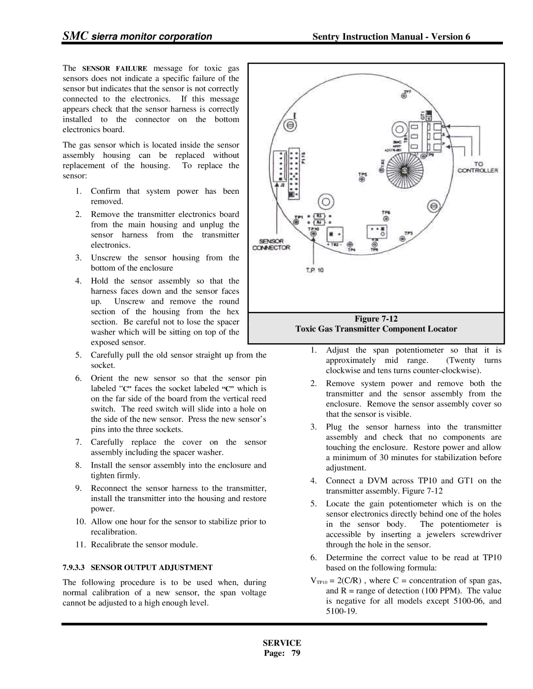
Figure 7-12


Toxic Gas Transmitter Component Locator


washer which will be sitting on top of the


exposed sensor.


1.

Adjust

the

span

potentiometer so

that

it

is


5.

Carefully pull the old sensor straight up from the


approximately

mid

range.

(Twenty

turns


socket.


clockwise and tens turns counter-clockwise).


6.

Orient

the

new

sensor

so that

the

sensor pin


2.

Remove system

power and

remove

both

the


labeled “C” faces the socket labeled “C” which is


transmitter

and

the sensor assembly

from

the


on the far side of the board from the vertical reed


enclosure. Remove the sensor assembly cover so


switch. The reed switch will slide into a hole on


that the sensor is visible.


the side of the new sensor. Press the new sensor’s


3.

Plug the sensor harness into the

transmitter


pins into the three sockets.


7.

Carefully

replace the

cover

on

the sensor


assembly and

check

that no

components

are


touching the enclosure. Restore power and allow


assembly including the spacer washer.


a minimum of 30 minutes for stabilization before


8.

Install the sensor assembly into the enclosure and


adjustment.


tighten firmly.


4. Connect a DVM across TP10 and GT1 on the


9.

Reconnect the sensor harness to the transmitter,


transmitter assembly. Figure 7-12


install the transmitter into the housing and restore


5.

Locate

the

gain

potentiometer

which

is

on

the


power.


sensor electronics directly behind one of the holes


10.

Allow one hour for the sensor to stabilize prior to


in the

sensor

body.

The potentiometer is


recalibration.


accessible by inserting a jewelers screwdriver


11.

Recalibrate the sensor module.


through the hole in the sensor.


6. Determine the correct value to be read at TP10


7.9.3.3

SENSOR OUTPUT ADJUSTMENT


based on the following formula:


The following procedure is to be used when, during

VTP10 = 2(C/R) , where C = concentration of span gas,


normal calibration of a new sensor, the span voltage


and R = range of detection (100 PPM). The value


cannot be adjusted to a high enough level.


is negative for all models except 5100-06, and


5100-19.


SERVICE


Page:

79


Page 85
Image 85
Sentry Industries 5000 instruction manual Toxic Gas Transmitter Component Locator, Service

5000 specifications

Sentry Industries 5000 is a cutting-edge security and surveillance system designed for both commercial and residential applications. With its robust features, state-of-the-art technologies, and user-friendly interface, the Sentry Industries 5000 has established itself as a leader in the security industry.

One of the primary features of the Sentry Industries 5000 is its advanced motion detection system. Equipped with smart sensors, the system effectively differentiates between human movement and other disturbances, such as pets or passing vehicles. This smart detection reduces false alarms, providing peace of mind and ensuring that users are alerted only when genuine security threats are present.

Another key aspect of the Sentry Industries 5000 is its high-definition camera capabilities. The system supports 4K resolution, delivering crystal-clear video quality that allows for easy identification of individuals and objects. Additionally, the cameras are equipped with night vision technology, enabling effective monitoring even in low-light conditions. The ability to pan, tilt, and zoom (PTZ) enhances the coverage area, allowing users to monitor large spaces with ease.

Connectivity is a cornerstone of the Sentry Industries 5000, incorporating both Wi-Fi and Ethernet options for flexible installation. It also features seamless integration with smart home devices, allowing users to control their security system via mobile apps or voice commands. This interoperability enables customized security settings, alert configurations, and device interconnectivity for a cohesive smart environment.

Another standout characteristic of the Sentry Industries 5000 is its cloud storage capability. Users can choose to save their footage locally or on the cloud, which ensures that data is secure and accessible from anywhere at any time. The flexibility in storage solutions caters to various user needs and preferences.

Data encryption and secure access protocols are critical components of the Sentry Industries 5000, providing robust protection against unauthorized access and hacking attempts. The system includes two-factor authentication for added security, ensuring that user data remains confidential and protected.

Moreover, the user-friendly interface of the Sentry Industries 5000 simplifies the process of monitoring and managing security features. With intuitive controls and easy-to-navigate menus, users can set up their systems quickly and efficiently.

In summary, the Sentry Industries 5000 is a comprehensive security solution that excels in features, technology, and user experience. With advanced motion detection, high-definition surveillance, flexible connectivity, and strong security measures, it stands out as an ideal choice for those looking to enhance their security measures in an increasingly challenging world.