SMC sierra monitor corporation

Sentry Instruction Manual - Version 6

5.3.1.2 LOCAL CALIBRATION

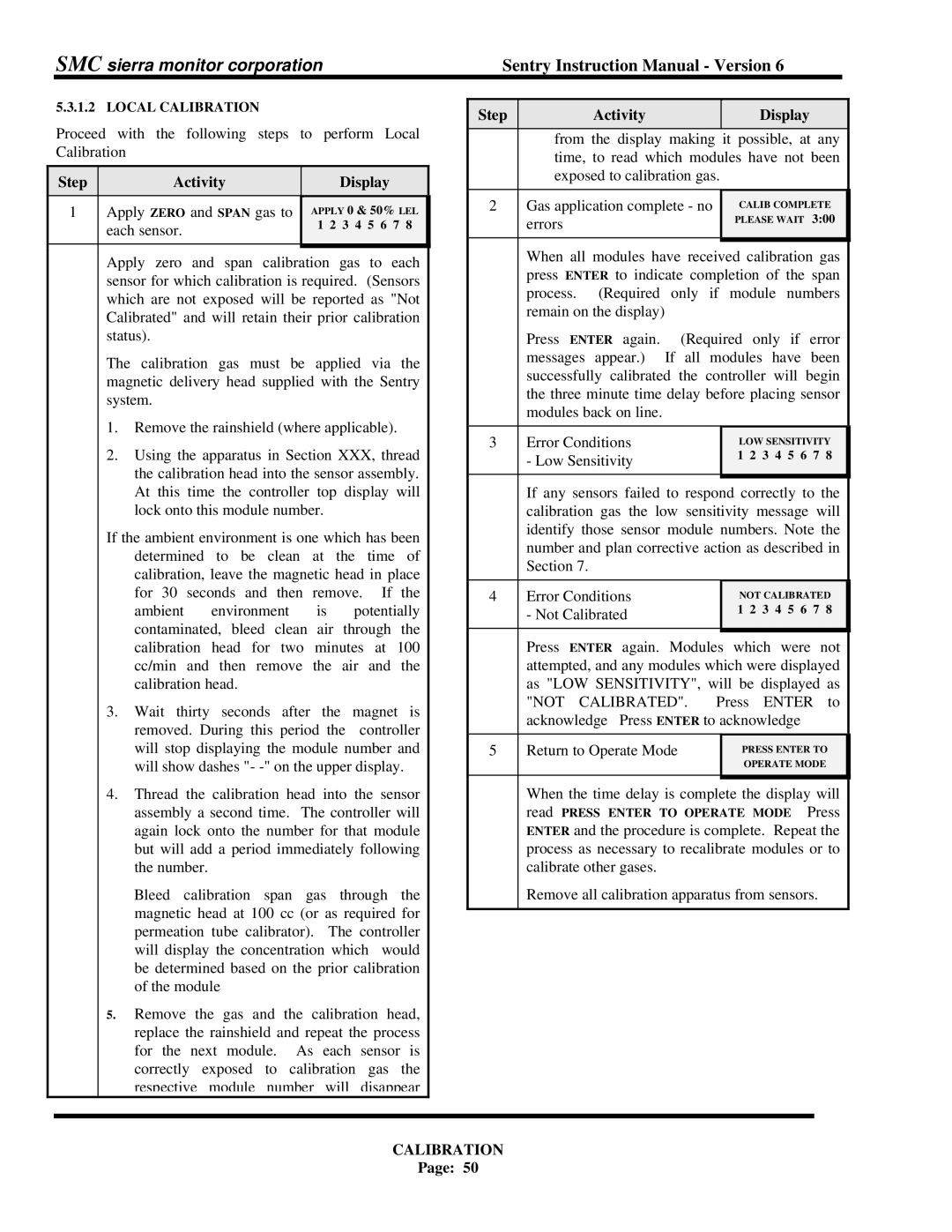
Proceed with the following steps to perform Local Calibration


Step


Activity


Display


1


Apply ZERO and SPAN gas to

APPLY 0 & 50% LEL


each sensor.


1 2 3 4 5 6 7 8


Apply zero and span calibration gas to each


sensor for which calibration is required. (Sensors


which are not exposed will be reported as "Not


Calibrated" and will retain their prior calibration


status).


The calibration gas must be applied via the


magnetic delivery head supplied with the Sentry


system.


1. Remove the rainshield (where applicable).


2. Using the apparatus in Section XXX, thread


the calibration head into the sensor assembly.


At this time the controller top display will


lock onto this module number.


If the ambient environment is one which has been


determined to be clean at the time of


calibration, leave the magnetic head in place


for 30 seconds and then remove. If the


ambient

environment

is

potentially


contaminated, bleed clean air through the


calibration head for two minutes at 100


cc/min and then remove the air and the


calibration head.


3.Wait thirty seconds after the magnet is removed. During this period the controller will stop displaying the module number and will show dashes "- -" on the upper display.

4.Thread the calibration head into the sensor assembly a second time. The controller will again lock onto the number for that module but will add a period immediately following the number.

Bleed calibration span gas through the magnetic head at 100 cc (or as required for permeation tube calibrator). The controller will display the concentration which would be determined based on the prior calibration of the module

5.Remove the gas and the calibration head, replace the rainshield and repeat the process for the next module. As each sensor is correctly exposed to calibration gas the respective module number will disappear


Step


Activity


Display


from the display making

it possible, at any


time, to read which modules have not been


exposed to calibration gas.


2


Gas application complete - no


CALIB COMPLETE


errors


PLEASE WAIT 3:00


When all modules have received calibration gas


press ENTER to indicate completion of the span


process. (Required only if module numbers


remain on the display)


Press ENTER again. (Required only if error


messages appear.) If all modules

have been


successfully calibrated the controller will begin


the three minute time delay before placing sensor


modules back on line.


3


Error Conditions


LOW SENSITIVITY


- Low Sensitivity


1 2 3 4 5 6 7 8


If any sensors failed to respond correctly to the


calibration gas the low sensitivity message will


identify those sensor module numbers. Note the


number and plan corrective action as described in


Section 7.


4


Error Conditions


NOT CALIBRATED


- Not Calibrated


1 2 3 4 5 6 7 8


Press ENTER again. Modules which were not


attempted, and any modules which were displayed


as "LOW SENSITIVITY", will be displayed as


"NOT CALIBRATED".

Press

ENTER to


acknowledge Press ENTER to acknowledge


5


Return to Operate Mode


PRESS ENTER TO


OPERATE MODE


When the time delay is complete the display will read PRESS ENTER TO OPERATE MODE Press ENTER and the procedure is complete. Repeat the process as necessary to recalibrate modules or to calibrate other gases.

Remove all calibration apparatus from sensors.

CALIBRATION

Page: 50

Page 56
Image 56
Sentry Industries 5000 instruction manual Not Calibrated

5000 specifications

Sentry Industries 5000 is a cutting-edge security and surveillance system designed for both commercial and residential applications. With its robust features, state-of-the-art technologies, and user-friendly interface, the Sentry Industries 5000 has established itself as a leader in the security industry.

One of the primary features of the Sentry Industries 5000 is its advanced motion detection system. Equipped with smart sensors, the system effectively differentiates between human movement and other disturbances, such as pets or passing vehicles. This smart detection reduces false alarms, providing peace of mind and ensuring that users are alerted only when genuine security threats are present.

Another key aspect of the Sentry Industries 5000 is its high-definition camera capabilities. The system supports 4K resolution, delivering crystal-clear video quality that allows for easy identification of individuals and objects. Additionally, the cameras are equipped with night vision technology, enabling effective monitoring even in low-light conditions. The ability to pan, tilt, and zoom (PTZ) enhances the coverage area, allowing users to monitor large spaces with ease.

Connectivity is a cornerstone of the Sentry Industries 5000, incorporating both Wi-Fi and Ethernet options for flexible installation. It also features seamless integration with smart home devices, allowing users to control their security system via mobile apps or voice commands. This interoperability enables customized security settings, alert configurations, and device interconnectivity for a cohesive smart environment.

Another standout characteristic of the Sentry Industries 5000 is its cloud storage capability. Users can choose to save their footage locally or on the cloud, which ensures that data is secure and accessible from anywhere at any time. The flexibility in storage solutions caters to various user needs and preferences.

Data encryption and secure access protocols are critical components of the Sentry Industries 5000, providing robust protection against unauthorized access and hacking attempts. The system includes two-factor authentication for added security, ensuring that user data remains confidential and protected.

Moreover, the user-friendly interface of the Sentry Industries 5000 simplifies the process of monitoring and managing security features. With intuitive controls and easy-to-navigate menus, users can set up their systems quickly and efficiently.

In summary, the Sentry Industries 5000 is a comprehensive security solution that excels in features, technology, and user experience. With advanced motion detection, high-definition surveillance, flexible connectivity, and strong security measures, it stands out as an ideal choice for those looking to enhance their security measures in an increasingly challenging world.