MICROWAVE MEASUREMENT PROCEDURE
TABLE OF CONTENTS
WARNING TO SERVICE PERSONNEL
WARNING TO SERVICE PERSONNEL
BEFORE SERVICING
When the testing is completed
WARNING TO SERVICE PERSONNEL
After repairing
Before Servicing
C. Leakage test
MICROWAVE MEASUREMENT PROCEDURE
B. Preparation for testing
A. Requirements
If provided, Vent Hood, Fan assembly, Cooling Fan Motor
DANGER
1440 Bridge Gate Dr Diamond Bar, CA
SERVICE MANUAL
DESCRIPTION
MICROWAVE DRAWER SPECIFICATION
GROUNDING INSTRUCTIONS
GENERAL INFORMATION
OFF CONDITION
POWER LEVEL P-0 TO P-90 COOKING
OPERATION
DESCRIPTION OF OPERATING SEQUENCE
MICROWAVE
SENSOR COOKING CONDITION
Cooking Sequence
DOOR
SCHEMATIC OFF CONDITION
CLOSED, COOK OFF CONDITTION
Before testing
TEST PROCEDURES
PROCEDURE
A TOUCH CONTROL PANEL ASSEMBLY TEST
C RELAY TEST
COMPONENT TEST
B KEY UNIT TEST
The rated AC voltage is not present between
Check supply voltage and oven power cord
DEFROST TEST
STEPS
Water load cooking test
TESTING METHOD FOR AH SENSOR AND/OR CONTROL UNIT
F AH SENSOR TEST Checking the initial sensor cooking condition
R1, R2 22Ω ± 1% 1/2W R3 4.3kΩ ± 5% 1/4W R4 1MΩ ± 5% 1/4W
CHECKING CONTROL UNIT
H THERMAL CUT-OUT TEST
Refer to the disassembly instructions found on Page
G MAGNETRON ASSEMBLY TEST
MICROWAVE OUTPUT POWER
K MONITOR SWITCH TEST
I SECONDARY INTERLOCK SWITCH TEST
J STOP SWITCH TEST
L BLOWN MONITOR FUSE TEST
M POWER TRANSFORMER TEST
5 Indicator Circuit
TOUCH CONTROL PANEL ASSEMBLY
Control Unit and Power Unit
4 Reset Circuit
Power source voltage +5V
DESCRIPTION OF LSI IC-1
Power source voltage 0V GND
Internal clock oscillation frequency setting input
Signal similar to P23
Signal
Segment data signal
Signal coming from touch key
Signal to synchronize LSI with commercial power source frequency
Magnetron high-voltage circuit driving signal
Common relay driving signal. Square Waveform 60Hz
Signal to sound buzzer
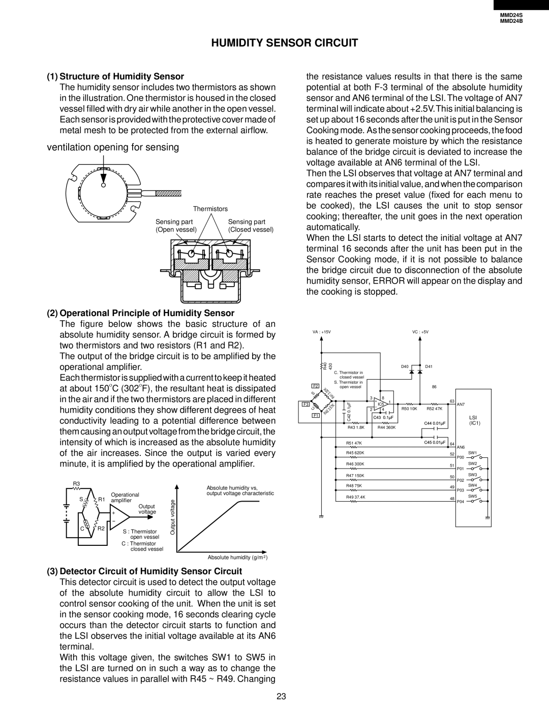
2 Operational Principle of Humidity Sensor
HUMIDITY SENSOR CIRCUIT
ventilation opening for sensing
1 Structure of Humidity Sensor
2. Servicing of Touch Control Panel
TOUCH CONTROL PANEL SERVICING
1 Servicing the touch control panel with power supply of the oven
4. Other Precautions
3. Soldering
PRECAUTIONS FOR USING LEAD-FREE SOLDER
2. Using lead-free wire solder
1. Employing lead-free solder
To prevent an electric shock, take the following pre- cautions
COMPONENT REPLACEMENT AND ADJUSTMENT PROCEDURE
WARNING FOR WIRING
WARNING AGAINST HIGH VOLTAGE
MICROWAVE DRAWER DISASSEMBLY
Un-hook/Attach Ground to metal Tab on Back Plate
POWER CORD REPLACEMENT
Un-hook/Attach Black AC Wire to Top Terminal
Un-hook/Attach White AC Wire to Bottom Terminal
After adjustment, check the following
STOP SWITCH, SECONDARY INTERLOCK SWITCH AND MONITOR SWITCH REMOVAL
STOP SWITCH, SECONDARY INTERLOCK SWITCH AND MONITOR SWITCH ADJUSTMENT
Re-install
1. Follow the Microwave Drawer disassembly as previously
DRAWER ASSEMBLY AND CHOKE REMOVAL
DRAWER SUPPORT ANGLE REMOVAL
DRAWER/SLIDE RAIL REMOVAL
Actuator adjustment
SWITCH ANGLE REMOVAL/ADJUSTMENT
SWITCH ANGLE REMOVAL
ACTUATOR REMOVAL/ADJUSTMENT
Installation
AUTO DRAWER GEAR REMOVAL/INSTALLATION
Bottom cover
RACK GEAR REMOVAL
to Back Plate
HIGH VOLTAGE COMPONENTS
CN-A
Figure S-2. Power Unit Circuit
MICRO
FM A
F G H
UNIT
CONTROL
UNIT
A B C D E F G H
Figure S-4. Printed Wiring Board of Power Unit
2.5A
UnitControlof
5.PrintedWiringBoard
COPYRIGHT 2008 BY DACOR, INC ALL RIGHTS RESERVED