Connecting Peripheral Equipment
■ Connection with
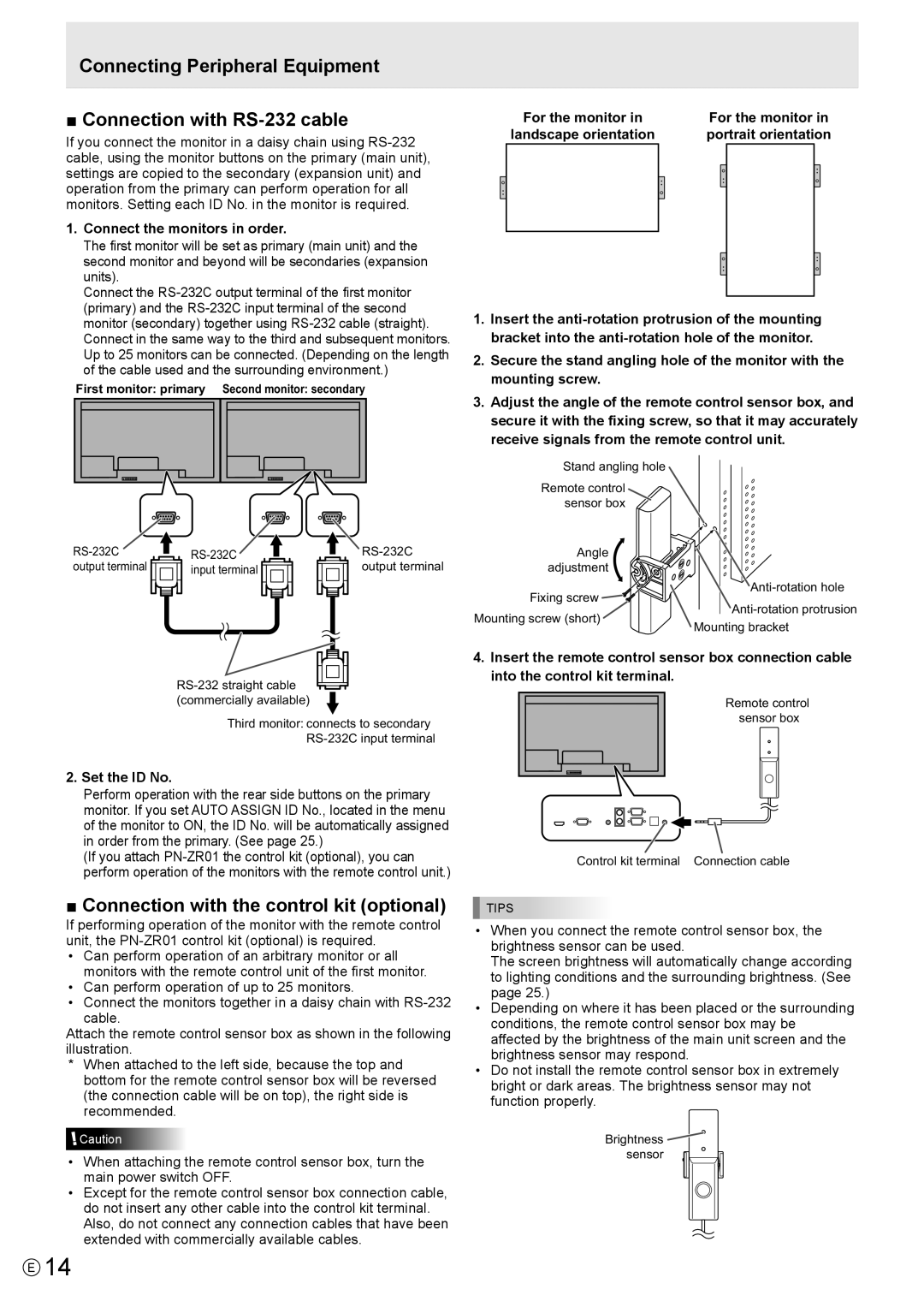
If you connect the monitor in a daisy chain using
1.Connect the monitors in order.
The first monitor will be set as primary (main unit) and the second monitor and beyond will be secondaries (expansion units).
Connect the
First monitor: primary Second monitor: secondary
output terminal | input terminal | output terminal |
Third monitor: connects to secondary
2. Set the ID No.
Perform operation with the rear side buttons on the primary monitor. If you set AUTO ASSIGN ID No., located in the menu of the monitor to ON, the ID No. will be automatically assigned in order from the primary. (See page 25.)
(If you attach
■ Connection with the control kit (optional)
If performing operation of the monitor with the remote control unit, the
•Can perform operation of an arbitrary monitor or all monitors with the remote control unit of the first monitor.
•Can perform operation of up to 25 monitors.
•Connect the monitors together in a daisy chain with
cable.
Attach the remote control sensor box as shown in the following illustration.
*When attached to the left side, because the top and bottom for the remote control sensor box will be reversed (the connection cable will be on top), the right side is recommended.
![]() Caution
Caution
•When attaching the remote control sensor box, turn the main power switch OFF.
•Except for the remote control sensor box connection cable, do not insert any other cable into the control kit terminal. Also, do not connect any connection cables that have been extended with commercially available cables.
For the monitor in | For the monitor in | ||
landscape orientation | portrait orientation | ||
|
|
|
|
|
|
|
|
1.Insert the
2.Secure the stand angling hole of the monitor with the mounting screw.
3.Adjust the angle of the remote control sensor box, and secure it with the fixing screw, so that it may accurately receive signals from the remote control unit.
Stand angling hole
Remote control sensor box
Angle |
| |
adjustment |
| |
Fixing screw | ||
Mounting screw (short) | ||
Mounting bracket | ||
|
4.Insert the remote control sensor box connection cable into the control kit terminal.
Remote control sensor box
Control kit terminal Connection cable
TIPS
•When you connect the remote control sensor box, the brightness sensor can be used.
The screen brightness will automatically change according to lighting conditions and the surrounding brightness. (See page 25.)
•Depending on where it has been placed or the surrounding conditions, the remote control sensor box may be affected by the brightness of the main unit screen and the brightness sensor may respond.
•Do not install the remote control sensor box in extremely bright or dark areas. The brightness sensor may not function properly.
Brightness ![]() sensor
sensor ![]()
E14