Initialization (Reset)/Functional Restriction Setting (FUNCTION)
You can return the settings to their
1.If using the remote control unit, press SIZE until “F” is displayed in the upper left area of the screen, then
while “F” is being displayed, press ![]() ,
, ![]() ,
, ![]() , and
, and
![]() in that order.
in that order.
If using the monitor buttons, press ![]() and
and ![]() at the same time until “F” is displayed in the upper left area of the screen, then while “F” is being displayed, press
at the same time until “F” is displayed in the upper left area of the screen, then while “F” is being displayed, press
![]() and
and ![]() at the same time.
at the same time.
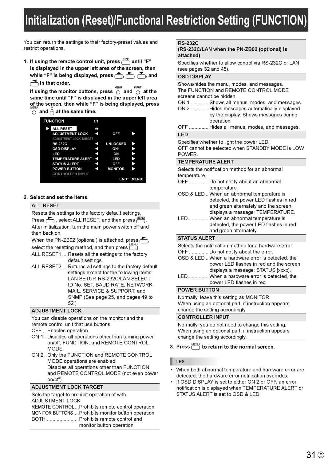
FUNCTION | 1/1 | ||
|
|
| |
| ALL RESET |
|
|
| ADJUSTMENT LOCK | OFF | |
| ADJUSTMENT LOCK TARGET |
| |
| UNLOCKED | ||
| OSD DISPLAY | ON1 | |
| LED | ON | |
| TEMPERATURE ALERT | LED | |
| STATUS ALERT | OFF | |
| POWER BUTTON | MONITOR | |
| CONTROLLER INPUT |
| |
END…[MENU]
2. Select and set the items.
ALL RESET
Resets the settings to the factory default settings.
Press ![]() , select ALL RESET, and then press MENU .
, select ALL RESET, and then press MENU .
After initialization, turn the main power switch off and then back on.
When the ![]() ,
,
select the resetting method, and then press MENU .
ALL RESET1 ....Resets all the settings to the factory
default settings.
ALL RESET2 ....Returns all settings to the factory default
settings except for the following items: LAN SETUP,
ADJUSTMENT LOCK
You can disable operations on the monitor and the remote control unit that use buttons.
OFF ...Enables operation.
ON 1 ..Disables all operations other than turning power on/off, FUNCTION, and REMOTE CONTROL MODE.
ON 2 ..Only the FUNCTION and REMOTE CONTROL MODE operations are enabled.
Disables all operations other than FUNCTION and REMOTE CONTROL MODE (not even power on/off).
ADJUSTMENT LOCK TARGET
Sets the target to prohibit operation of with
ADJUSTMENT LOCK.
REMOTE CONTROL.... | Prohibits remote control operation |
MONITOR BUTTONS.... | Prohibits monitor button operation |
BOTH | Prohibits remote control and |
| monitor button operation |
Specifies whether to allow control via
OSD DISPLAY
Shows/hides the menu, modes, and messages. The FUNCTION and REMOTE CONTROL MODE screens cannot be hidden.
ON 1 | Shows all menus, modes, and messages. |
ON 2 | Hides messages automatically displayed |
| by the display. Shows messages during |
| operation. |
OFF | Hides all menus, modes, and messages. |
LED
Specifies whether to light the power LED.
OFF cannot be selected when STANDBY MODE is LOW POWER.
TEMPERATURE ALERT
Selects the notification method for an abnormal temperature.
OFF | Do not notify about an abnormal |
| temperature. |
OSD & LED .. | When an abnormal temperature is |
| detected, the power LED flashes in red |
| and green alternately and the screen |
| displays a message: TEMPERATURE. |
LED | When an abnormal temperature is |
| detected, the power LED flashes in red |
| and green alternately. |
STATUS ALERT | |
Selects the notification method for a hardware error. | |
OFF | Do not notify about the error. |
OSD & LED .. | When a hardware error is detected, the |
| power LED flashes in red and the screen |
| displays a message: STATUS [xxxx]. |
LED | When a hardware error is detected, the |
| power LED flashes in red. |
POWER BUTTON
Normally, leave this setting as MONITOR.
When using an optional part, if instruction appears, change the setting accordingly.
CONTROLLER INPUT
Normally, you do not need to change this setting. When using an optional part, if instruction appears, change the setting accordingly.
3. Press MENU to return to the normal screen.
TIPS
•When both abnormal temperature and hardware error are detected, the hardware error notification overrides.
•If OSD DISPLAY is set to either ON 2 or OFF, an error notification is displayed when TEMPERATURE ALERT or STATUS ALERT is set to OSD & LED.