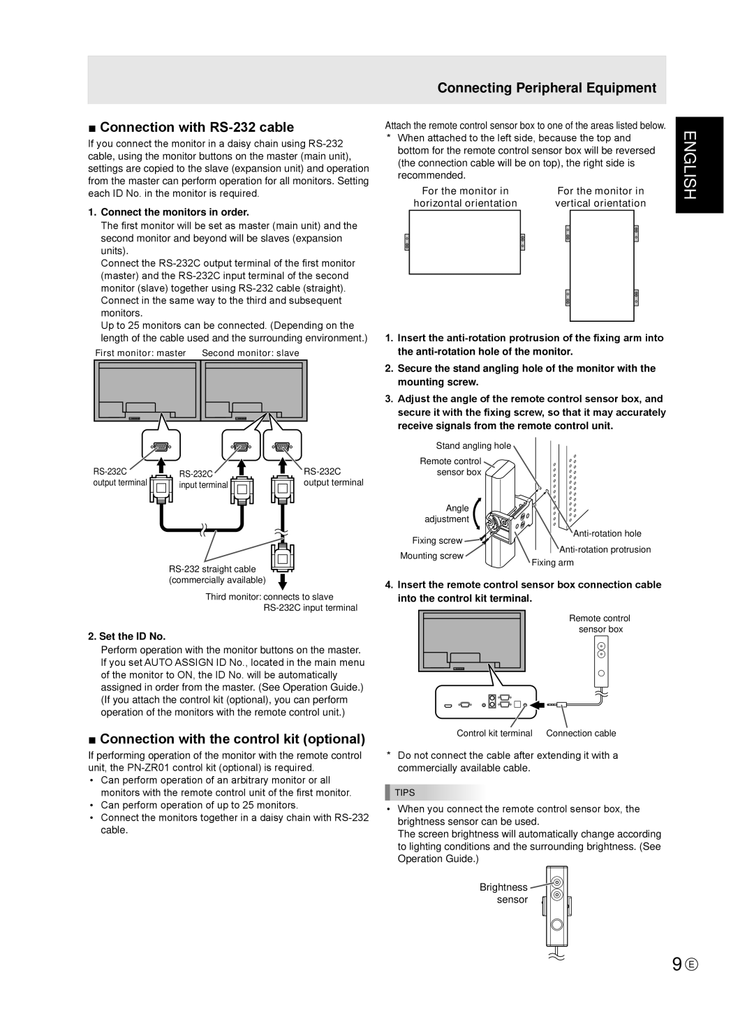
■ Connection with RS-232 cable
If you connect the monitor in a daisy chain using
1.Connect the monitors in order.
The first monitor will be set as master (main unit) and the second monitor and beyond will be slaves (expansion units).
Connect the
Up to 25 monitors can be connected. (Depending on the length of the cable used and the surrounding environment.)
First monitor: master Second monitor: slave
output terminal | input terminal | output terminal |
Third monitor: connects to slave
2. Set the ID No.
Perform operation with the monitor buttons on the master. If you set AUTO ASSIGN ID No., located in the main menu of the monitor to ON, the ID No. will be automatically assigned in order from the master. (See Operation Guide.) (If you attach the control kit (optional), you can perform operation of the monitors with the remote control unit.)
■ Connection with the control kit (optional)
If performing operation of the monitor with the remote control unit, the
•Can perform operation of an arbitrary monitor or all monitors with the remote control unit of the first monitor.
•Can perform operation of up to 25 monitors.
•Connect the monitors together in a daisy chain with
Connecting Peripheral Equipment
Attach the remote control sensor box to one of the areas listed below.
*When attached to the left side, because the top and bottom for the remote control sensor box will be reversed (the connection cable will be on top), the right side is recommended.
For the monitor in | For the monitor in | ||
horizontal orientation | vertical orientation | ||
|
|
|
|
|
|
|
|
1.Insert the
2.Secure the stand angling hole of the monitor with the mounting screw.
3.Adjust the angle of the remote control sensor box, and secure it with the fixing screw, so that it may accurately receive signals from the remote control unit.
Stand angling hole
Remote control sensor box
Angle |
| |
adjustment |
| |
Fixing screw | ||
Mounting screw | ||
Fixing arm | ||
|
4.Insert the remote control sensor box connection cable into the control kit terminal.
Remote control sensor box
Control kit terminal | Connection cable |
*Do not connect the cable after extending it with a commercially available cable.
TIPS
•When you connect the remote control sensor box, the brightness sensor can be used.
The screen brightness will automatically change according to lighting conditions and the surrounding brightness. (See Operation Guide.)
Brightness ![]() sensor
sensor ![]()
ENGLISH
9 E