Supplied Components
If any component should be missing, please contact your dealer.
Liquid Crystal Display Monitor: 1 | |
Cable clamp: 2 | Operation manual: 1 |
Power cord | Protection cover: 4 |
*Sharp Corporation holds authorship rights to the Utility Disk program. Do not reproduce it without permission.
* For environmental protection!
Do not dispose of batteries in household waste. Follow the disposal instructions for your area.
ENGLISH
Connecting Peripheral Equipment
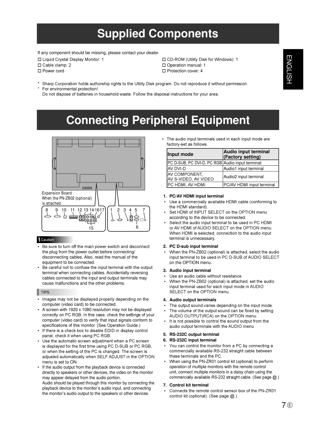
Expansion Board
When the PN-ZB02 (optional) is attached
8 | 9 | 10 | 11 | 12 13 14 1617 | 1 | 2 | 3 | 4 | 5 | 7 | |
|
|
|
|
|
|
|
|
|
|
|
|
|
|
|
|
|
|
|
|
|
|
|
|
156
![]() Caution
Caution
•Be sure to turn off the main power switch and disconnect the plug from the power outlet before connecting/ disconnecting cables. Also, read the manual of the equipment to be connected.
•Be careful not to confuse the input terminal with the output terminal when connecting cables. Accidentally reversing cables connected to the input and output terminals may cause malfunctions and the other problems.
TIPS
•Images may not be displayed properly depending on the computer (video card) to be connected.
•A screen with 1920 x 1080 resolution may not be displayed correctly on PC RGB. In this case, check the settings of your computer (video card) to verify that input signals conform to specifications of this monitor. (See Operation Guide.)
•If there is a check box to disable EDID in display control panel, check it when using PC RGB.
•Use the automatic screen adjustment when a PC screen is displayed for the first time using PC
•If the audio output from the playback device is connected directly to speakers or other devices, the video on the monitor may appear delayed from the audio portion.
Audio should be played through this monitor by connecting the playback device to the monitor’s audio input, and connecting the monitor’s audio output to the speakers or other devices.
•The audio input terminals used in each input mode are
Input mode | Audio input terminal | |
(Factory setting) | ||
| ||
PC | Audio input terminal | |
AV | Audio1 input terminal | |
AV component, | Audio2 input terminal | |
AV | ||
| ||
PC HDMI, AV HDMI | PC/AV HDMI input terminal |
1. PC/AV HDMI input terminal
•Use a commercially available HDMI cable (conforming to the HDMI standard).
•Set HDMI of INPUT SELECT on the OPTION menu according to the device to be connected.
•Select the audio input terminal to be used in PC HDMI or AV HDMI of AUDIO SELECT on the OPTION menu. When HDMI is selected, connection to the audio input terminal is unnecessary.
2. PC D-sub input terminal
•When the
3. Audio input terminal
•Use an audio cable without resistance.
•When the
4. Audio output terminals
•The output sound varies depending on the input mode.
•The volume of the output sound can be fixed by setting AUDIO OUTPUT(RCA) on the OPTION menu.
•It is not possible to control the sound output from the audio output terminals with the AUDIO menu.
5.RS-232C output terminal
6.RS-232C input terminal
•You can control the monitor from a PC by connecting a commercially available
•When using the
7. Control kit terminal
•Connects the remote control sensor box of the
7 E