Initial Installation
QUALIFIED INSTALLERS ONLY
HORIZONTAL INSTALLATION:
1.Set the appliance in the desired location. Check to determine if wall studs or roof rafters are in the way when the venting system is attached. If this is the case, you may want to adjust the location of the appliance.
2.Direct vent pipe and fittings are designed with special
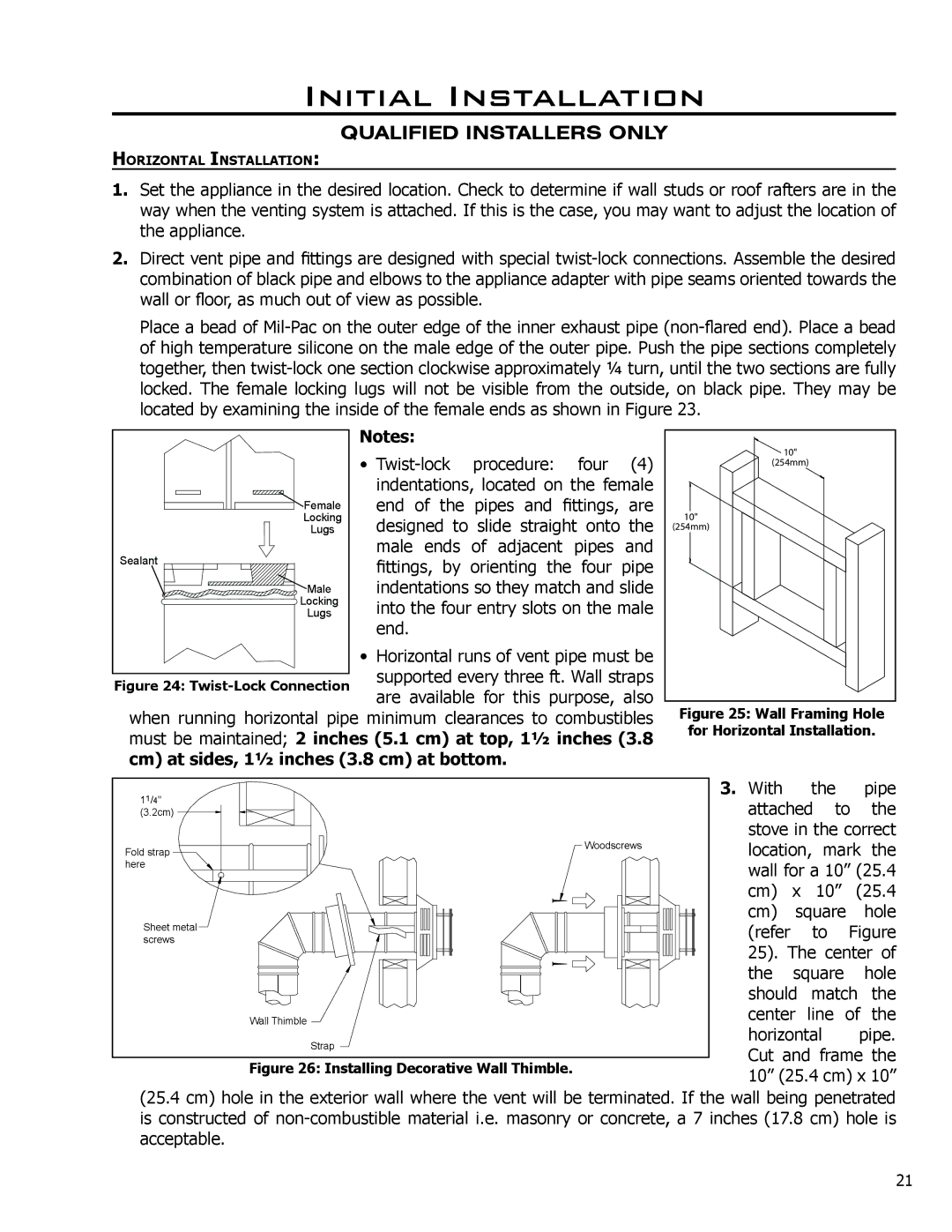
Place a bead of
Notes: | ||
• | ||
| indentations, located on the female | |
Female | end of the pipes and fittings, are | |
Locking | designed to slide straight onto the | |
Lugs | ||
Sealant | male ends of adjacent pipes and | |
fittings, by orienting the four pipe | ||
| ||
Male | indentations so they match and slide | |
Locking | into the four entry slots on the male | |
Lugs | ||
| end. | |
• Horizontal runs of vent pipe must be supported every three ft. Wall straps are available for this purpose, also
when running horizontal pipe minimum clearances to combustibles must be maintained; 2 inches (5.1 cm) at top, 11⁄2 inches (3.8 cm) at sides, 11⁄2 inches (3.8 cm) at bottom.
��� |
������� |
��� |
������� |
Figure 25: Wall Framing Hole for Horizontal Installation.
11/4" |
|
(3.2cm) |
|
Fold strap | Woodscrews |
| |
here |
|
Sheet metal |
|
screws |
|
| Wall Thimble |
| Strap |
Figure 26: Installing Decorative Wall Thimble.
3. With the pipe attached to the stove in the correct location, mark the wall for a 10” (25.4 cm) x 10” (25.4 cm) square hole (refer to Figure 25). The center of the square hole should match the center line of the
horizontal pipe. Cut and frame the 10” (25.4 cm) x 10”
(25.4 cm) hole in the exterior wall where the vent will be terminated. If the wall being penetrated is constructed of
21