Initial Installation
QUALIFIED INSTALLERS ONLY
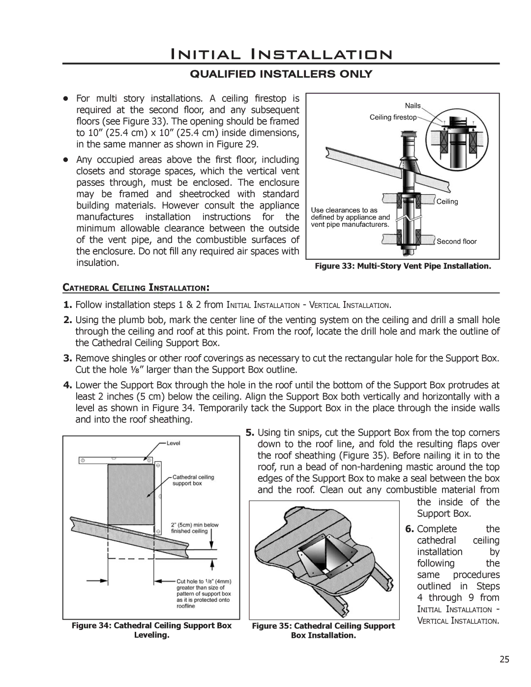
•For multi story installations. A ceiling firestop is required at the second floor, and any subsequent floors (see Figure 33). The opening should be framed to 10” (25.4 cm) x 10” (25.4 cm) inside dimensions, in the same manner as shown in Figure 29.
•Any occupied areas above the first floor, including closets and storage spaces, which the vertical vent passes through, must be enclosed. The enclosure may be framed and sheetrocked with standard building materials. However consult the appliance manufactures installation instructions for the minimum allowable clearance between the outside of the vent pipe, and the combustible surfaces of the enclosure. Do not fill any required air spaces with
insulation. | Figure 33: |
|
CATHEDRAL CEILING INSTALLATION:
1.Follow installation steps 1 & 2 from INITIAL INSTALLATION - VERTICAL INSTALLATION.
2.Using the plumb bob, mark the center line of the venting system on the ceiling and drill a small hole
through the ceiling and roof at this point. From the roof, locate the drill hole and mark the outline of the Cathedral Ceiling Support Box.
3.Remove shingles or other roof coverings as necessary to cut the rectangular hole for the Support Box. Cut the hole 1⁄8” larger than the Support Box outline.
4.Lower the Support Box through the hole in the roof until the bottom of the Support Box protrudes at least 2 inches (5 cm) below the ceiling. Align the Support Box both vertically and horizontally with a level as shown in Figure 34. Temporarily tack the Support Box in the place through the inside walls and into the roof sheathing.
Figure 34: Cathedral Ceiling Support Box
Leveling.
5.Using tin snips, cut the Support Box from the top corners down to the roof line, and fold the resulting flaps over the roof sheathing (Figure 35). Before nailing it in to the roof, run a bead of
| the inside | of | the | ||
| |||||
| Support Box. |
| |||
| 6. Complete |
| the | ||
| cathedral | ceiling | |||
| installation |
| by | ||
| following |
| the | ||
| same | procedures | |||
| outlined | in | Steps | ||
| 4 through | 9 | from | ||
| INITIAL INSTALLATION - | ||||
| VERTICAL INSTALLATION. | ||||
Figure 35: Cathedral Ceiling Support | |||||
|
|
|
| ||
Box Installation. |
|
|
|
| |
25