Manuals
/
Sherwood
/
Household Appliance
/
Stove
Sherwood
EG40 DV
owner manual
Parts Diagram Chassis
Models:
EG40 DV
1
34
39
39
Download
39 pages
45.94 Kb
31
32
33
34
35
36
37
38
Troubleshooting
Specs
Install
Parts list
Parts Diagram Chassis
Warranty
Maintenance
Assembly of Venting Kit
Remove door to clean glass
Log Placement
Page 34
Image 34
Parts Diagram - Chassis
��
�
��
��
��
�
��
��
��
��
��
��
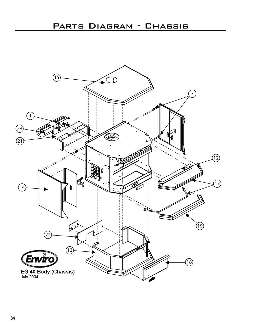
EG 40 Body (Chassis)
July 2004
34
Page 33
Page 35
Page 34
Image 34
Page 33
Page 35
Contents
EG40 DV
Safety Precautions
General
Table of Contents
Codes And Approvals
Vented GAS Fireplace Heater EG40 DV NG/LPG
Specifications
EG40 Exterior Dimensions
For Your Safety Read Completely Before Operating
Operating Instructions
There is a separate venturies for each burner, see Figure
Component Sound & Reason
Maintenance and Service
Removing the Door
Burner is lined up
Kit Parts List
Conversion Kit Installation
Must be not visible
Removing valve Screw
Initial Installation
Qualified Installers only
Common Vertical Installation
Do not interfere with the structural integrity of the walls
Vent Termination Restrictions
KIT Components
Assembly of Venting Kit
Manufacturer Trade Name Nominal Sizes
SV4EBR45
Vent restrictor ring
End of the pipes and fittings, are
Installing Vent Cap with Vinyl Siding Stand-Off
Assemble the desired lengths of black pipe
Use of Wall Straps
Multi-Story Vent Pipe Installation
Insulation
33a-2002 Test Methods and the Resulting ITS/WH
Must be connected to a grounding rod
Must be bolted securely to the floor
Manifold Pressure
Natural Gas Propane Front Burner
Rear Burner
Min. Manifold Pressure
Secondary Installation
Log Placement
Remove door to clean glass
Trouble Shooting
Problem Possible Cause Solution
Parts List
T. Nova Valve Convertible 50-1421
Parts List
Parts Diagram Chassis
Parts Diagram Gas Tray & Door
Warranty
To the Dealer
Warranty
Warranty
Installation Data Sheet
Top
Page
Image
Contents