Reversing cutting head for flush cutting operations
WARNING!
Before performing any work on the
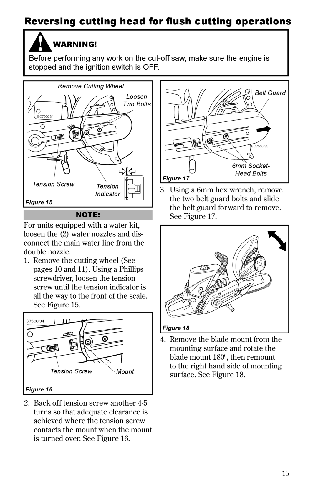
Remove Cutting Wheel | |
| Loosen |
| Two Bolts |
EC7500.34 |
|
Tension Screw | Tension |
| Indicator |
Figure 15 |
|
| NOTE: |
For units equipped with a water kit, loosen the (2) water nozzles and dis- connect the main water line from the double nozzle.
1.Remove the cutting wheel (See pages 10 and 11). Using a Phillips screwdriver, loosen the tension screw until the tension indicator is all the way to the front of the scale. See Figure 15.
C7500.34 |
|
Tension Screw | Mount |
Figure 16 |
|
| Belt Guard |
| EC7500.35 |
| 6mm Socket- |
Figure 17 | Head Bolts |
|
3.Using a 6mm hex wrench, remove the two belt guard bolts and slide the belt guard forward to remove. See Figure 17.
Figure 18
4.Remove the blade mount from the mounting surface and rotate the blade mount 1800, then remount to the right hand side of mounting surface. See Figure 18.
2.Back off tension screw another
15