Assembly
This unit comes fully assembled with the exception of the cutting attachment shield and cutting attachment.
IMPORTANT!
The terms “left”,
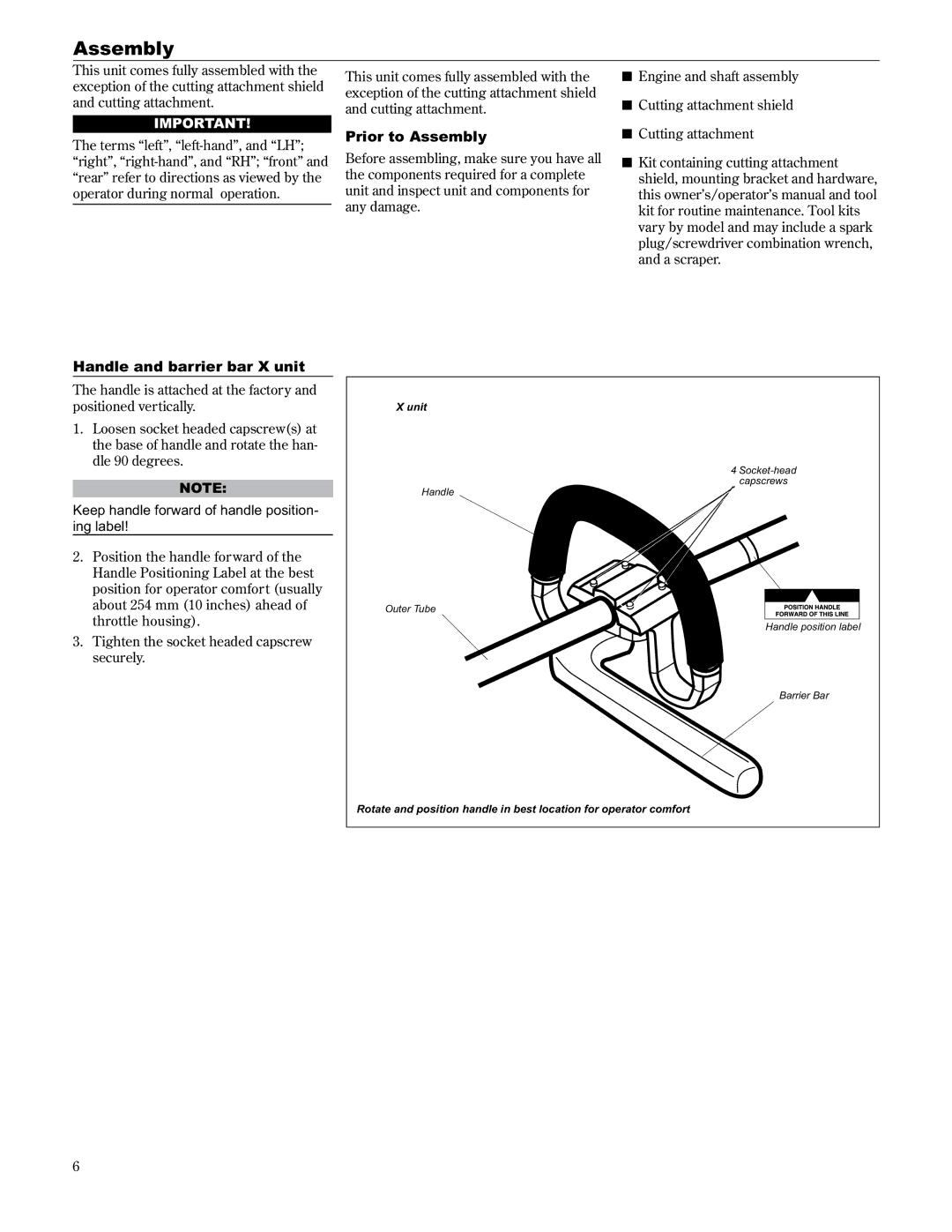
Handle and barrier bar X unit
The handle is attached at the factory and positioned vertically.
1.Loosen socket headed capscrew(s) at the base of handle and rotate the han dle 90 degrees.
NOTE:
Keep handle forward of handle position- ing label!
2.Position the handle forward of the Handle Positioning Label at the best position for operator comfort (usually about 254 mm (10 inches) ahead of throttle housing).
3.Tighten the socket headed capscrew securely.
This unit comes fully assembled with the exception of the cutting attachment shield and cutting attachment.
Prior to Assembly
Before assembling, make sure you have all the components required for a complete unit and inspect unit and components for any damage.
X unit
Handle
Outer Tube
ŶEngine and shaft assembly
ŶCutting attachment shield
ŶCutting attachment
ŶKit containing cutting attachment shield, mounting bracket and hardware, this owner’s/operator’s manual and tool kit for routine maintenance. Tool kits vary by model and may include a spark plug/screwdriver combination wrench, and a scraper.
4
Handle position label
Barrier Bar
Rotate and position handle in best location for operator comfort
6