Assembly (continued)
Adjust throttle lever free play
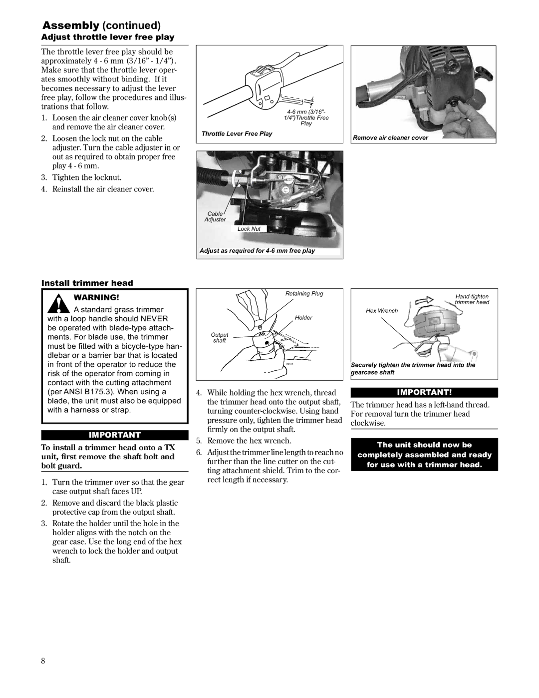
The throttle lever free play should be approximately 4 - 6 mm (3/16” - 1/4”). Make sure that the throttle lever oper- ates smoothly without binding. If it becomes necessary to adjust the lever free play, follow the procedures and illus- trations that follow.
1.Loosen the air cleaner cover knob(s) and remove the air cleaner cover.
2.Loosen the lock nut on the cable adjuster. Turn the cable adjuster in or out as required to obtain proper free play 4 - 6 mm.
3.Tighten the locknut.
4.Reinstall the air cleaner cover.
1/4”)Throttle Free
Play
Throttle Lever Free Play
Cable
Adjuster
Lock Nut
Adjust as required for
Remove air cleaner cover
Install trimmer head
WARNING!
A standard grass trimmer with a loop handle should NEVER be operated with
Retaining Plug
Holder
Output
shaft
Hex Wrench
Securely tighten the trimmer head into the gearcase shaft
(per ANSI B175.3). When using a blade, the unit must also be equipped with a harness or strap.
IMPORTANT
To install a trimmer head onto a TX unit, first remove the shaft bolt and bolt guard.
1.Turn the trimmer over so that the gear case output shaft faces UP.
2.Remove and discard the black plastic protective cap from the output shaft.
3.Rotate the holder until the hole in the holder aligns with the notch on the gear case. Use the long end of the hex wrench to lock the holder and output shaft.
4.While holding the hex wrench, thread the trimmer head onto the output shaft, turning
5.Remove the hex wrench.
6.Adjust the trimmer line length to reach no further than the line cutter on the cut- ting attachment shield. Trim to the cor- rect length if necessary.
IMPORTANT!
The trimmer head has a
The unit should now be
completely assembled and ready
for use with a trimmer head.
8