480V Metal-Enclosed Switchgear
LV Power Circuit Breakers
General
4
480V
RL Breaker Accessories / Modifications (cont’d)
Operation Counter
A
Undervoltage Trip Device
The undervoltage trip device protects against a drop in normal bus voltage and functions to directly trip the breaker. Pickup occurs at 85 percent or less of rated value and dropout between 30 and 60 percent of rated value. Pickup and dropout are individually adjustable. Instantaneous or
Table 4.7 Undervoltage Trip Ratings
Nominal Control | Pickup | Dropout | ||
Voltage |
| Voltage | Voltage | |
| 120 | 100 | 60 | |
60 Hz AC | 240 or | — | — | |
| 480a | |||
DC | 48 | 40 | 24 | |
125 | 105 | 62 | ||
| ||||
aNot available. Use 120 VAC undervoltage device with appropriate 240/120V or voltage transformer in cubicle.
Electrically Operated Interlock
This can be added to interlock two break- ers, preventing both from being closed at the same time. These electromechanical devices add an additional solenoid that must be energized before the breaker can be closed. When the interlock is de- energized, the breaker is held
Table 4.8 Interlock Coil Ratings
|
| Voltage Range | ||
Nominal Control | Pickup | Dropout | ||
Voltage |
| Voltage | Voltage | |
60 Hz AC | 120 | 104 | 36 | |
240 | 208 | 72 | ||
| ||||
| 48 | 38 | 15 | |
DC | 125 | 100 | 38 | |
| 250 | 200 | 75 | |
Automatic Trip Alarm Contact (with or without Lockout) (Bell Alarm)
The bell alarm contact is operated when the trip actuator operates in response to the Static Trip III trip unit. It indicates when the circuit breaker has tripped as a result of the static trip unit. The contact can control a local or remote auxiliary alarm for indication of an automatic trip or, by wiring in series with a breaker clos- ing coil, for interlocking to prevent circuit breaker closure until the circuit is reset. The contact must be reset manually or electrically (optional). The manually reset switch is available with a
If desired, a mechanical lockout option may be provided. This substitutes a manual reset for the automatically reset tripping actuator. In this case the breaker is held trip free until the lockout is manually reset.
Table 4.9 Bell Alarm Contact Ratings
Nominal |
| Bell Alarm Contact Ratings | |||
| (Amperes) |
|
| ||
Control |
|
|
| ||
Voltage |
| Continuous | Make | Break | |
60 Hz |
| 120 | 10.0 | 10.0 | 10.0 |
AC |
| 240 | 10.0 | 10.0 | 10.0 |
|
| 48 | 0.5 | 10.0 | 0.5 |
DC |
| 125 | 0.5 | 10.0 | 0.5 |
|
| 250 | 0.25 | 10.0 | 0.25 |
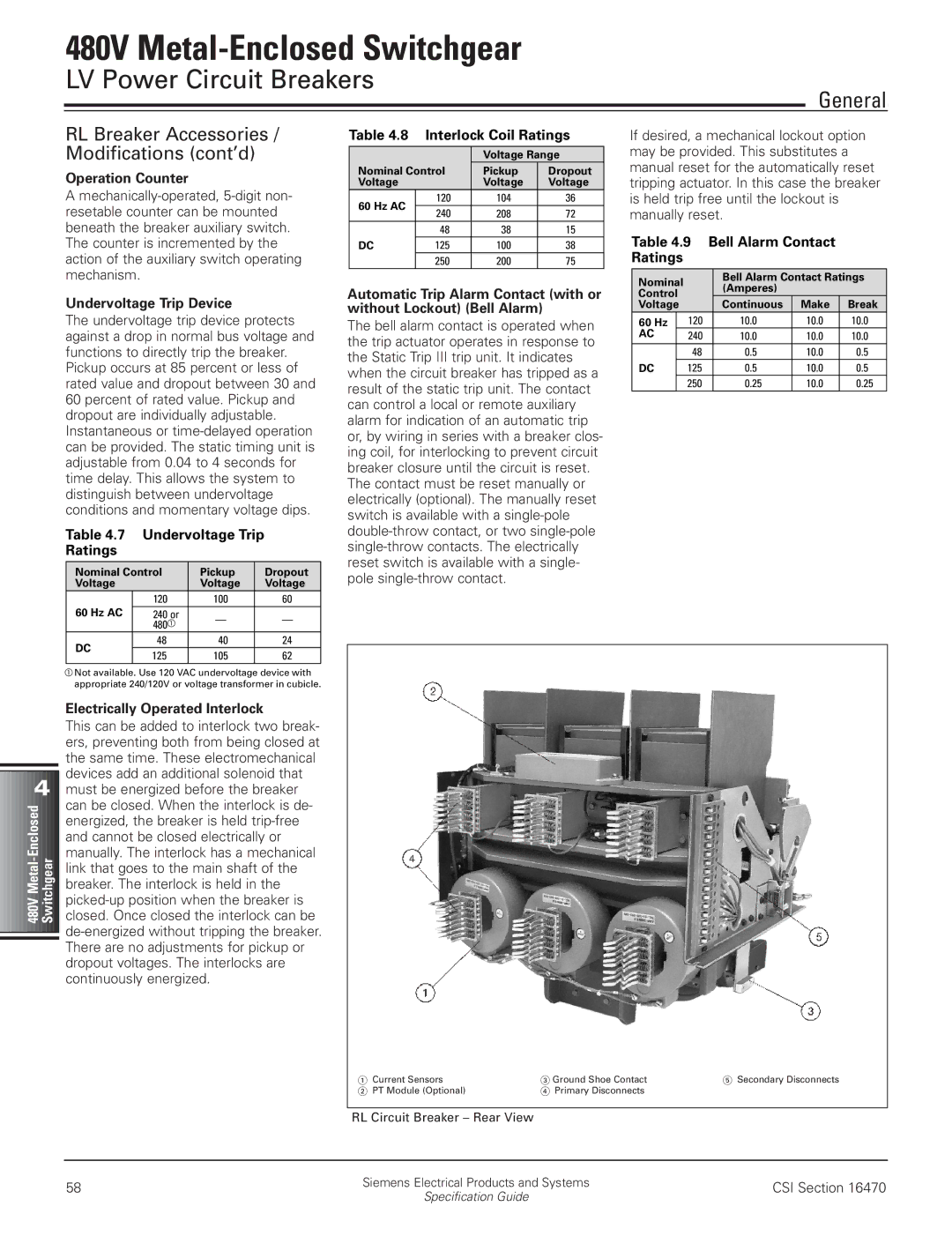
1 | Current Sensors | 3 Ground Shoe Contact | 5 Secondary Disconnects |
2 | PT Module (Optional) | 4 Primary Disconnects |
|
RL Circuit Breaker – Rear View
58 | Siemens Electrical Products and Systems | CSI Section 16470 | |
Specification Guide | |||
|
|