Getting Started with HC15
Confidential / Preliminary
s
2.3Installing the Hardware
To properly connect the HC15 module and all accessories to the DSB75 Board follow these steps:
•Check that the all switches of the DSB75 Board are set as described in the Appendix.
•Attach the adapter board to the
•Connect the one end of the mini antenna to the Hirose U.Fl connector of the DSB75 board and attach the other end to the Hirose U.FL connector located on the module’s top side.
•Mount the HC15 module upside down onto the
•Screw the external antenna (MiniMag) into the SMA connector on the DSB75. To improve the antenna performance use the metal plate for grounding. The external antenna should be positioned in the center of the metal plate.
•Connect the Western plug of the handset to the Western jack on the DSB75.
•Make sure that the power supply adapter is switched to 9 Volts, and connect the power cables to the red and black connectors of the DSB75.
•Plug the USB cable to the computer’s USB port and to the USB port of the DSB75. See Chapter 2.4 to continue.
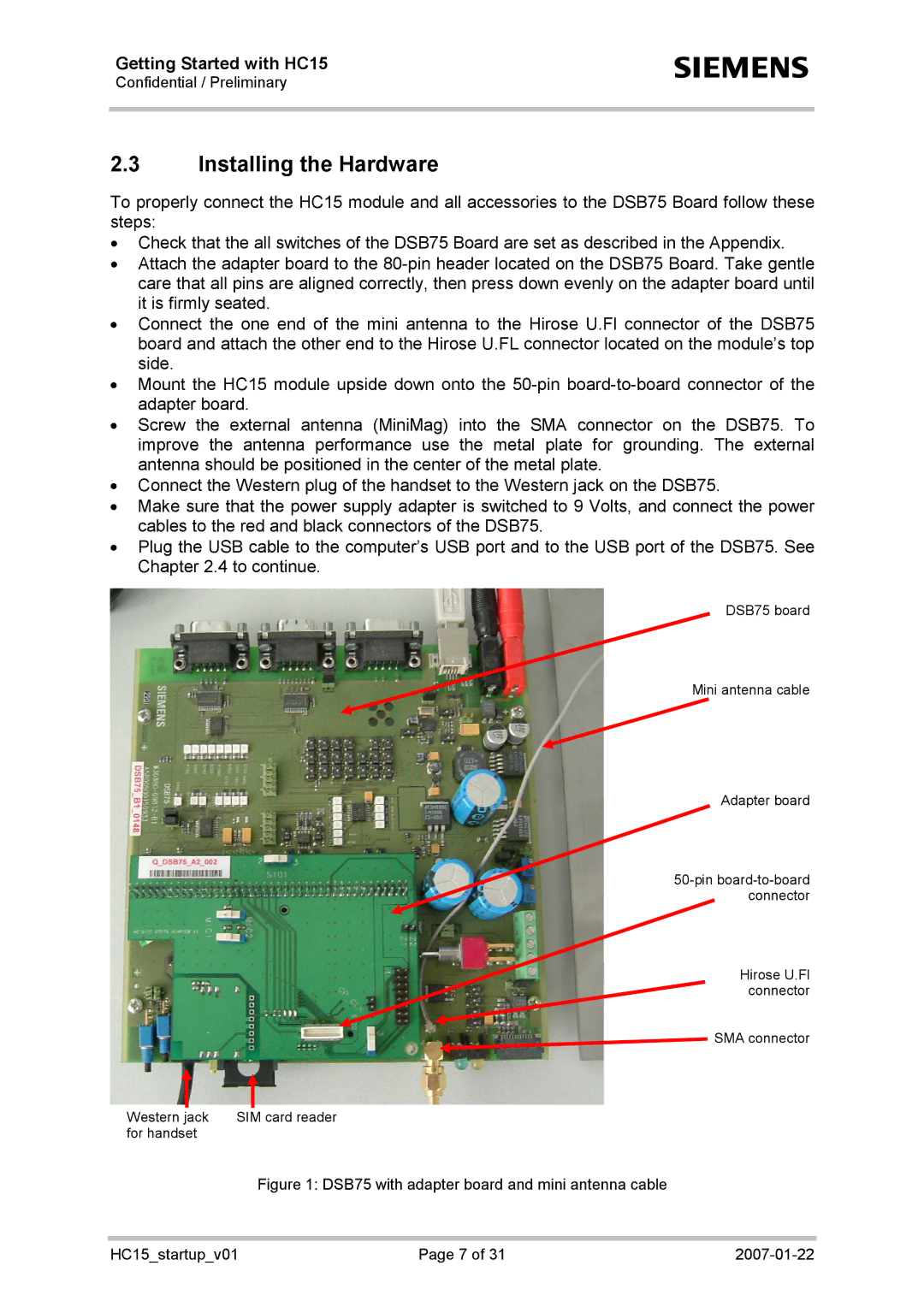
DSB75 board
Mini antenna cable
Adapter board
Hirose U.Fl connector
SMA connector
Western jack | SIM card reader |
for handset |
|
Figure 1: DSB75 with adapter board and mini antenna cable
HC15_startup_v01 | Page 7 of 31 |
|