Getting Started with HC15
Confidential / Preliminary
s
5 Appendix II
This chapter refers to the DSB75 Board and the adapter board needed to mount a HC15 module onto the DSB75 Board.
The focus is on the configuration of several switches you may be required to change for use with HC15. A detailed description of the DSB75 Board is given in [3].
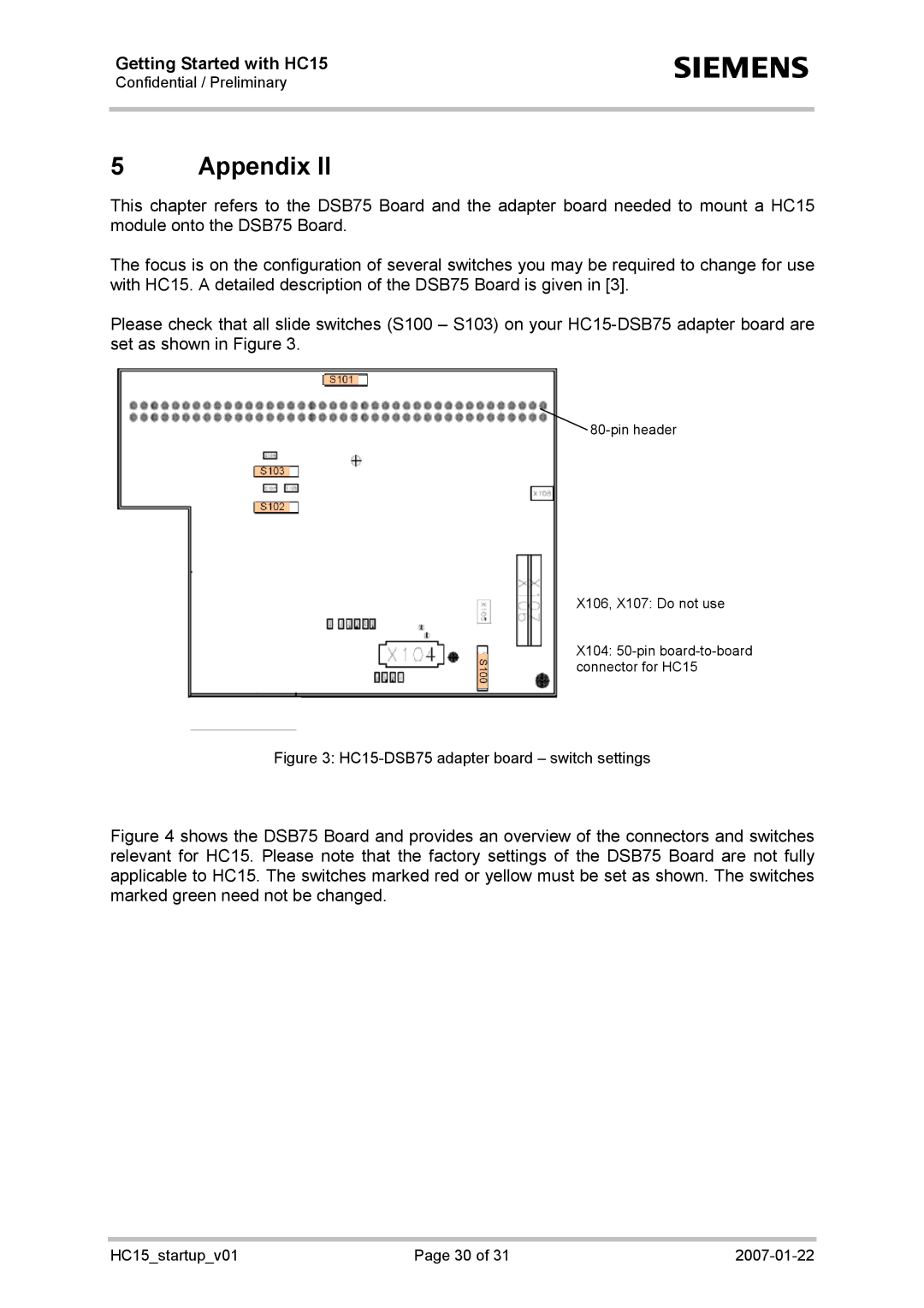
Please check that all slide switches (S100 – S103) on your
![]()
X106, X107: Do not use
X104:
Figure 3: HC15-DSB75 adapter board – switch settings
Figure 4 shows the DSB75 Board and provides an overview of the connectors and switches relevant for HC15. Please note that the factory settings of the DSB75 Board are not fully applicable to HC15. The switches marked red or yellow must be set as shown. The switches marked green need not be changed.
HC15_startup_v01 | Page 30 of 31 |