Industrial PC Simatic IPC427C
Simatic
Legal information
Table of contents
Table of contents
105
Index
Appendix
ESD guidelines
List of abbreviations
Preface
Introduction
Guideline to the Operating Instructions
Contents format Table of Contents
System expansions
Safety Instructions
General safety instructions
Repairs
ESD directives
Battery
Overview
Description
Applications
Features
Basic data
Drives and storage media
Monitoring and safety functions
Basic data Ports
Software Operating systems
Function Hard disk / SSD version Compact Flash card version
Windows Embedded Standard
Activation of Horm and creation of a Hiber File
Design
External Design
Device components Pos Description
Connection components
Ports and power supply
On/Off switch
Position of on/off switch Description
Operator controls
Status displays
Status displays
Meaning
Transport
Application planning
Unpacking and checking the delivery unit
Unpacking the device
Noting the device identification data
COA Label Windows Embedded Standard
Ambient and Environmental Conditions
Permitted mounting positions
Installing/mounting
Horizontal preferred position Permitted temperatures
Vertical Power supply at the top
Suspended
Upright mounting Permitted temperatures
Mounting information
Mounting the device
Mounting methods
Mounting on DIN rails
Mounting the device on DIN rails
Steps for mounting on DIN rails
Removing the device from the DIN rail
Installing/mounting 5.4 Mounting on DIN rails
Removing mounting clamps from the device
Installing brackets on the device
Steps for installing the mounting brackets
Mounting with mounting brackets
Mounting examples Material Bore diameter
Mounting/demounting the device
Mounting the vertical mounting bracket onto the device
Upright mounting
Connecting peripheral equipment
Connecting
To be noted before you connect the device
Connecting the 24 V DC power supply
Connecting
Steps for connecting the device to the 24 V DC power supply
Protective earth terminal
Protective ground connection
USB strain-relief
Steps for connecting the USB strain-relief
Commissioning
Factory state
Connections before commissioning
Requirements
Configuring the operating system
Commissioning Windows Embedded Standard
Basic commissioning initial startup
Switch off the device
Commissioning Windows XP Professional
Switch off the device
Commissioning other operating systems
Commissioning guide
Additional information
Integration into an Automation System
Ethernet
RS232
Integration into an Automation System 8.1 Overview
Simatic PC DiagMonitor software
Functions
Monitoring Functions
Simatic PC DiagBase software
Temperature monitoring
Temperature monitoring/display
WD monitoring times
Watchdog WD
Function
Watchdog reactions
Set EWF
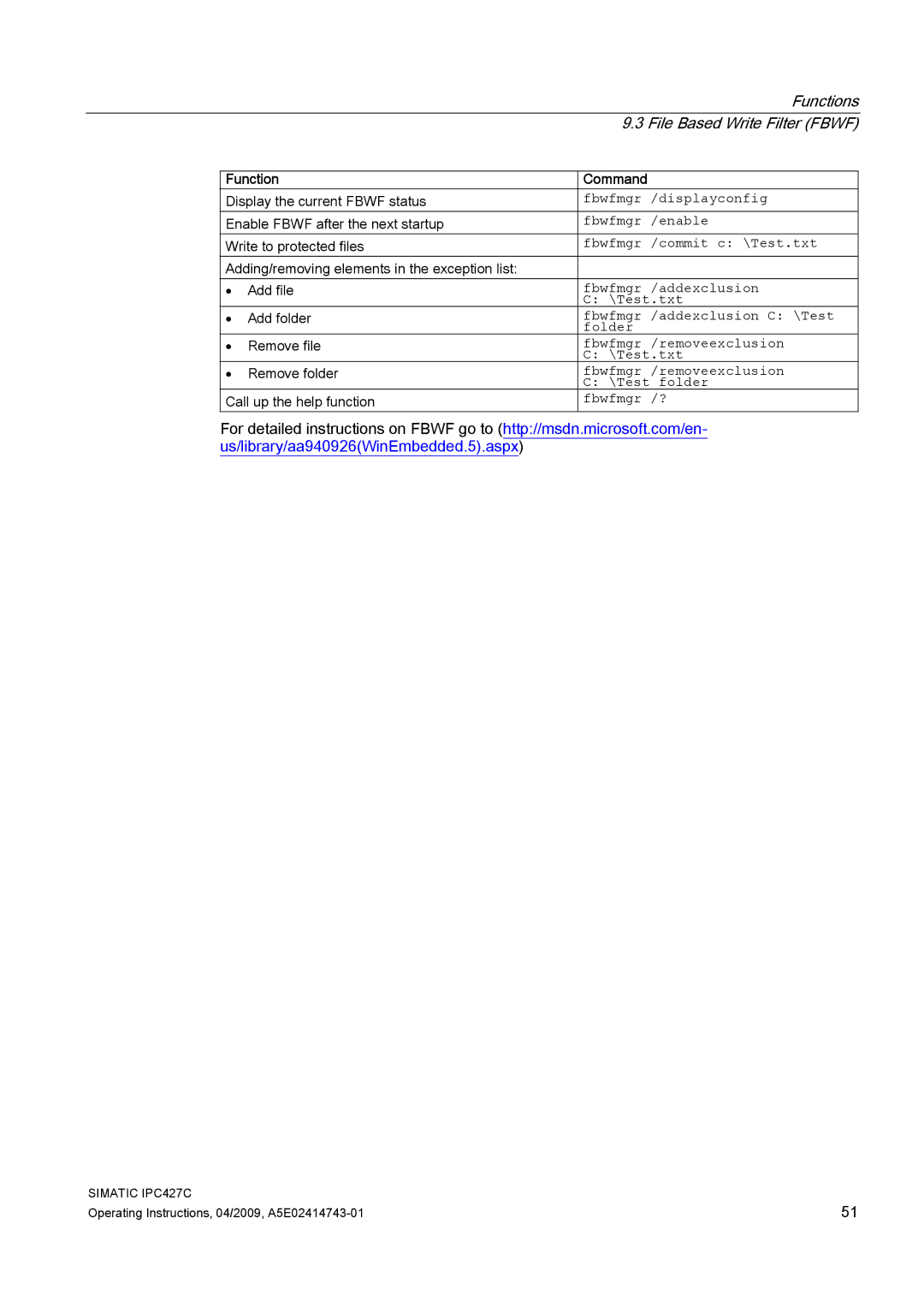
Function Command
Enhanced Write Filter EWF
Purpose and function
Ewfmgr c -enable
Special features for the use of Enhanced Write Filters EWF
Configuring Fbwf
File Based Write Filter Fbwf
Comparison between EWF and Fbwf
Functions
Sram buffer memory
Battery monitoring
Operation without monitor and keyboard
Preparation
Expansions and Configurations
Open the device front panel
Tools
Steps in opening the device front panel
Open the device
Memory expansion options
Installing the memory module
How to remove a memory module
Memory expansion
Installing a memory module
Display of the current memory configuration
How to install a memory module
Installing PCI-104 / PC/104 Plus modules
Mounting PCI-104 or PC/104 Plus modules
Mounting PCI-104 or PC/104-Plusmodules
Steps for mounting an expansion module
Mounting additional PCI-104 or PC/104-Plusmodules
Configuring/installing a PCI-104 or PC/104-Plusmodule
Installation options for Compact Flash cards
Installing/Removing Compact Flash Cards
Installing/removing an accessible Compact Flash card
Opening the module receptacle
Steps for opening the module receptacle
Steps for installing a Compact Flash card
Installing the Compact Flash card
Steps for removing a Compact Flash card
Removing the Compact Flash card
Steps for removing a built-in Compact Flash card
Installing/removing a built-in Compact Flash card
Carrying out repairs
Maintenance and Service
Removing and Installing Hardware Components
Repairs
Component Exchange interval
Preventive maintenance
How to remove a drive
Replacing hard disk or SSD drive
Removing drives
Installing a drive
Tool
Replace the backup battery
To be noted before you replace the battery
Disposal
Replacing the battery
Reconfiguring the Bios Setup
Steps for replacing the battery
Reinstalling the operating system
General installation procedure
Windows Embedded Standard
Restoring the factory state
Simatic IPC427C
Windows XP Professional
Setting up the operating system with the Recovery CD
Restoring the factory state
Maintenance and Service Reinstalling the operating system
Setting up the operating system via the Recovery CD/DVD
Booting with the Recovery CD/DVD
Partition setup
CDDRIVE\MUI
Installation of the operating system
Partitioning the hard disk
Setting up the partitions under Windows Embedded Standard
Partitioning data media
Partitioning the Compact Flash card
Partition Name Size File system
Setting up the partitions under Windows XP Professional
Installing drivers and software
Driver installation under Windows Embedded Standard
Installing drivers and software
Windows
Installing updates
Installing or updating application programs and drivers
Updating the operating system
Download from Bios update
Performing a Bios update
Creating an image
Data backup
On-screen error message Meaning / tip
Alarm, error and system messages
Boot error messages
On-screen error messages
Alarm, error and system messages 12.1 Boot error messages
Troubleshooting/FAQs
General problems
Problem Possible cause To correct or avoid error
Problems when using modules of third-party manufacturers
Safety
Technical specifications
General specifications
General specifications
General specifications Climatic Conditions
Horizontal mounting position
Vertical / portrait mounting position
Drives / storage media
General specifications Mech. Ambient conditions
Special Features
Motherboard
Status displays on the device
General specifications Ports
Maximum power consumption of the auxiliary components
Power requirements of the components
Current consumption Power consumption At 24 V rated voltage
14.3 Integrated DC power supply
Technical specifications
Typical power consumption
Overview of the dimensional drawings
Dimension drawings
Dimensional drawing of the device Front view
Dimension drawings of the device
Dimension drawings of the device with mounting brackets
100
101
Dimensional drawings of the device with expansion frames
Dimensional drawing of the blinding plate
Dimension drawing of the blanking plate
Dimension drawings Dimension drawing of the blanking plate
Detailed descriptions
Internal components
Overview of internal components
CPU
Technical features of the motherboard
Bios
Component Description Parameters Port
Port Position Description
External ports
Overview
16.1.3.2 COM1/2
DVI-I
USB port, 4 channel high current Pin no
16.1.3.5 USB
Ethernet RJ45 connection
Pin no Short description Description Input / output
Can bus
Profibus
Port Position Connector Description
Internal ports
16.1.4.2 Compact Flash card interface
PCI-104 or PCI part of the PC/104-Plus interface Pin no
PCI-104 or PC/104-Plus interface PCI part
Overview
Bios Setup
Bios Setup program
Changing the device configuration
Starting Bios Setup
Starting Bios Setup
Bios Setup menus
Menu Description
Menu layout
By submenus
Settings in the main menu
Main menu
Field Meaning
Serial ATA Port 0, Serial ATA Port
System time and date
Boot Options submenu
Keyboard Features submenu
Hardware Options submenu
Entry Meaning
PCI MPI / DP
Advanced Menu
Settings in the Advanced Menu
IO Device Configuration submenu
Ahci
Sata Configuration submenu
Security menu
12 Boot menu
Boot menu
13 Legacy submenu
Legacy
14 Boot Type Order field
129
15 Version menu example
Version menu
Exit Menu
Default Bios Setup entries
Documenting your device configuration
Bios Setup default settings
Legacy Boot Type Order
IO device configuration
Sata Configuration
Boot
Version
Simatic PC IPC427C Profibus
CPU ID
Currently allocated system resources
System resources
System resources used by the BIOS/DOS
PCI Interrupt Lines
Interrupt Interrupt type
Addresses
16.4 I/O Address Areas
Overview of the internal module registers
Overview of the internal module registers
Watchdog trigger register read only, address 066h
Meaning of the bits
Watchdog trigger register
Can base address register write only, address 066h
Output register LED 1 / 2 read/write, address 404Eh
Output register LED 1 / 2 read/write address 404Eh Bits
LED L2
Battery status tab read-only, address 50Fh
Sram address register
Sram address register
Declaration of conformity
Connecting peripherals
Guidelines and declarations
EMC directive
Software License Agreement
Approvals for the USA, Canada and Australia Product safety
Certificates and approvals
DIN ISO 9001 certificate
145
Service and support
Training center
Technical support
Definition of ESD
ESD Guidelines
Basic protective measures against electrostatic discharge
Electrostatic charging
Abbreviation Term Meaning
Abbreviations
Dram
FAQ
CRT
CSA
Html
HDA
HDD
HMI
ODD
NCQ
Nema
NMI
SSD
SO-DIMM
SOM
SPP
154
Glossary
Chipset
Configuration files
Configuration software
CE marking
Dual Core CPU
Device configuration
Disc-at-once
Drivers
Gender changer
ESD directive
File Based Write Filter EWF
Formatting
Interface, multi-point
Image
Intel VT
InterfaceInterface
LPT interface
License key
License key disk
Low-voltage directive
PC card
NEC Class
Operating system
Packet writing
Plug&Play
PIC mode
PEG interface
Pixel
PXE server
Recovery CD
Reset
Restore DVD
Session at once
Setup Bios Setup
Troubleshooting
Scsi interface
Wlan
Warm restart
166
Can
Index
Index
Simatic S7
170