OPERATION
Repeated trial starts can over heat the motor and result in motor burnout (particularly for across the line starting). If repeated trial starts are made, allow sufficient time between trials to permit heat to dis- sipate from windings and rotor to prevent overheating. Starting cur- rents are several times running cur- rents and heating varies as the square of the current.
After installation is completed, but before motor is put into regular ser- vice, make an initial start as fol- lows:
1. Check motor connections and |
VFD connections against wiring |
diagrams. |
2. Check voltage, phase, and all |
loaded drive parameters against |
a. If load is disconnected, run motor at no load long enough to be certain that no unusual conditions develop. Listen and feel for excessive noise, vibra- tion, clicking, or pounding. If present, stop motor immedi- ately. Investigate the cause and correct before putting motor in service.
b. If load is not disconnected, interrupt the starting cycle after motor has decelerated to a slow speed. Carefully observe for unusual conditions as motor coasts to a stop.
4.When checks are satisfactory, operate at minimum load and look for unusual conditions.
Increase load slowly to a maxi- mum. Check unit for satisfactory
operation.
Electric motors operating under nor- mal conditions become quite warm. Although some places may feel too hot to touch, the unit may be within operational limits. Use a thermo- couple to measure winding temper- ature when there is any concern.
The total temperature, not the tem- perature rise, is the measure of safe operation. Investigate the operating conditions if the total temperature measured by a ther- mocouple placed on the winding exceeds:
•275°F (135°C) for class “F” insula- tion
•302° F(150°C) for class “H” insula- tion
motor nameplate. If an auxiliary |
blower is supplied, check to see |
that it is wired and operating |
properly. The blower should be |
wired to a separate 60 hz power |
source. |
3. If possible, remove external load |
and turn shaft by hand to ensure |
free rotation. This may have |
been done during installation pro- |
cedure; if so, and conditions have |
not changed since, this check |
may not be necessary. |
VFD OPERATION
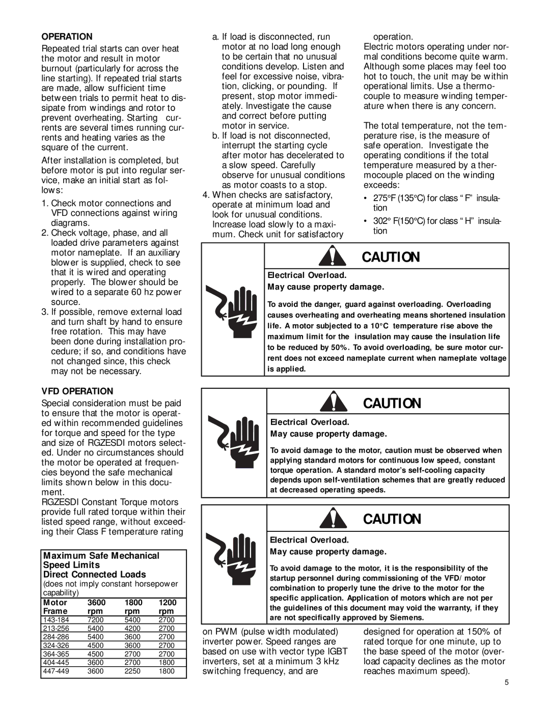
Special consideration must be paid to ensure that the motor is operat- ed within recommended guidelines for torque and speed for the type and size of RGZESDI motors select- ed. Under no circumstances should the motor be operated at frequen- cies beyond the safe mechanical limits shown below in this docu- ment.
RGZESDI Constant Torque motors provide full rated torque within their listed speed range, without exceed- ing their Class F temperature rating
Maximum Safe Mechanical
Speed Limits
Direct Connected Loads
(does not imply constant horsepower capability)
Motor 3600 1800 1200
Frame rpm rpm rpm
CAUTION |
Electrical Overload. |
May cause property damage. |
To avoid the danger, guard against overloading. Overloading |
causes overheating and overheating means shortened insulation |
life. A motor subjected to a 10°C temperature rise above the |
maximum limit for the insulation may cause the insulation life |
to be reduced by 50%. To avoid overloading, be sure motor cur- |
rent does not exceed nameplate current when nameplate voltage |
is applied. |
CAUTION
Electrical Overload.
May cause property damage.
To avoid damage to the motor, caution must be observed when applying standard motors for continuous low speed, constant torque operation. A standard motor’s
CAUTION
Electrical Overload.
May cause property damage.
To avoid damage to the motor, it is the responsibility of the startup personnel during commissioning of the VFD/ motor combination to properly tune the drive to the motor for the specific application. Application of motors which are not per the guidelines of this document may void the warranty, if they are not specifically approved by Siemens.
on PWM (pulse width modulated) | designed for operation at 150% of |
inverter power. Speed ranges are | rated torque for one minute, up to |
based on use with vector type IGBT | the base speed of the motor (over- |
inverters, set at a minimum 3 kHz | load capacity declines as the motor |
switching frequency, and are | reaches maximum speed). |
5
