Writing n words
Instruction | Slave |
| Function |
| Address | Number of |
| Number of |
|
| Word |
| Check- | ||||||||||||||||
| address |
| 0x10 |
| of first |
|
| words |
|
|
| bytes |
|
| value(s) |
| sum | ||||||||||||
|
|
|
|
|
|
|
|
|
| word |
|
|
|
|
|
| (max. 2) |
|
|
|
|
|
|
| CRC16 | ||||
| 1 byte |
| 1 byte |
| 2 bytes |
|
| 2 bytes |
|
|
| 1 byte |
|
| x byte(s) |
| 2 bytes | ||||||||||||
Reply |
|
|
|
|
|
|
|
|
|
|
|
|
|
|
|
|
|
|
|
| |||||||||
Slave address |
| Function 0x10 |
| Address of |
| Number of |
|
| Checksum | ||||||||||||||||||||
|
|
|
|
|
|
|
|
|
|
|
|
| first word |
| words |
|
|
| CRC16 | ||||||||||
|
| 1 byte |
|
|
|
| 1 byte |
|
| 2 bytes |
|
|
| 2 bytes |
|
|
| 2 bytes | |||||||||||
Example | Write |
|
|
|
|
|
|
|
|
|
|
|
|
|
| ||||||||||||||
| Word address = 0x0018 |
|
|
|
|
|
|
|
|
|
|
|
|
|
|
|
|
|
|
|
|
| |||||||
| Instruction: |
|
|
|
|
|
|
|
|
|
|
|
|
|
|
|
|
|
|
|
|
|
|
|
|
|
| ||
|
|
|
|
|
|
|
|
|
|
|
|
|
|
|
|
|
|
|
|
|
|
|
|
|
| ||||
| 0B |
| 10 |
| 00 |
| 18 |
| 00 |
| 02 |
| 04 |
| 00 |
| 00 |
| C1 |
| 20 |
|
| CRC16 |
| ||||
Reply:
0B
10
00
18
00
02
CRC16
Data type “char“ | The high byte must be transmitted first. |
|
| Example: Configuration code C111: “9030“ | |
| MOD bus: | 0B10 0024 00 02 04 0903 |
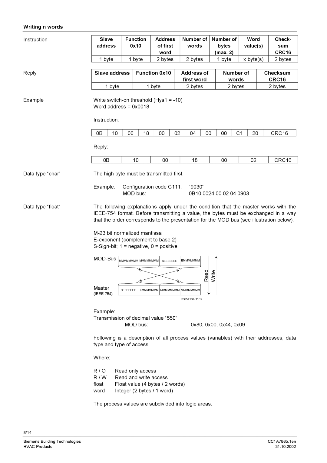
Data type “float“ | The following explanations apply under the condition that the master works with the | |
| ||
| that the order corresponds to the presentation for the MOD bus (see illustration below). | |
Read
Master | SEEEEEEE EMMMMMMM MMMMMMMM MMMMMMMM |
(IEEE 754)
7865z13e/1102
Write
Example: |
|
Transmission of decimal value “550“: |
|
MOD bus: | 0x80, 0x00, 0x44, 0x09 |
Following is a description of all process values (variables) with their addresses, data type and type of access.
Where: |
|
R / O | Read only access |
R / W | Read and write access |
float | Float value (4 bytes / 2 words) |
word | Integer (2 bytes / 1 word) |
The process values are subdivided into logic areas.
8/14
Siemens Building Technologies | CC1A7865.1en |
HVAC Products | 31.10.2002 |