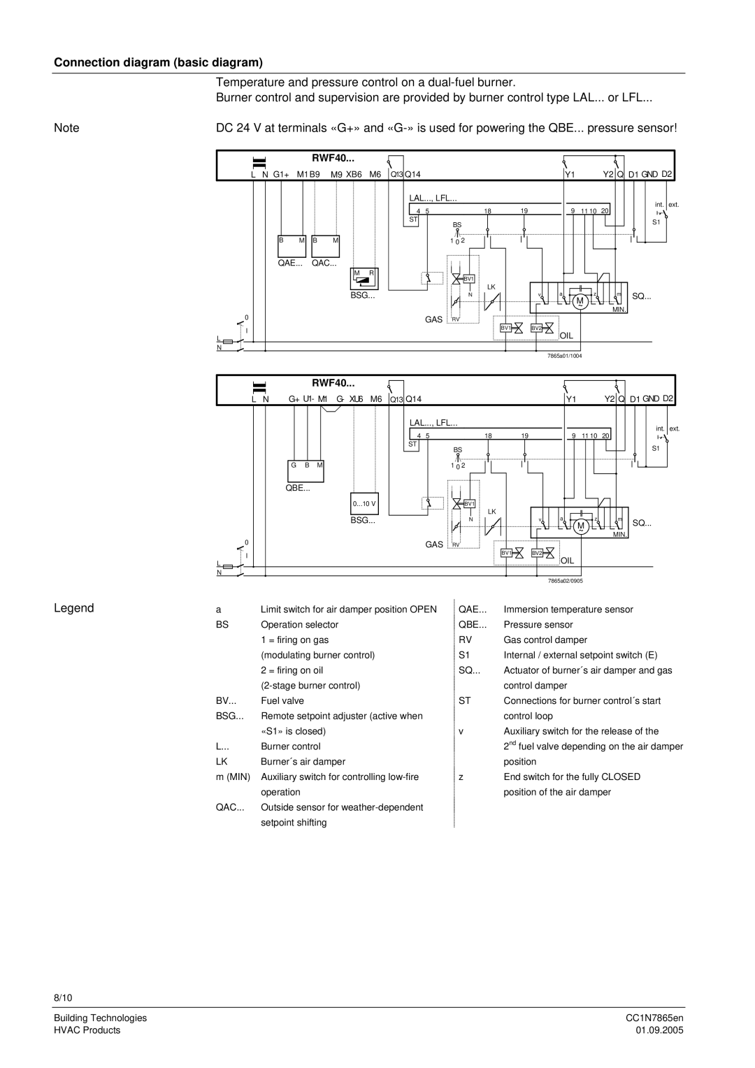
Connection diagram (basic diagram)
Temperature and pressure control on a
Burner control and supervision are provided by burner control type LAL... or LFL...
Note | DC 24 V at terminals «G+» and | |||||||||||||||||||||||||||
|
|
|
|
|
|
|
| RWF40... |
| Q13 Q14 |
|
|
|
|
|
|
|
|
|
|
| Y2 Q D1 GND D2 | ||||||
|
|
|
|
|
|
|
|
|
|
|
|
|
|
|
|
|
|
|
|
|
| |||||||
| L | N G1+ | M1B9 | M9 XB6 | M6 |
|
|
|
|
|
|
|
| Y1 |
| |||||||||||||
|
|
|
|
|
|
|
|
|
|
| LAL..., LFL... |
|
|
|
|
|
|
|
|
| int. | ext. | ||||||
|
|
|
|
|
|
|
|
|
|
|
| 4 | 5 | 18 |
| 19 |
|
| 9 | 11 10 | 20 |
| ||||||
|
|
|
|
|
|
|
|
|
|
|
|
|
|
| ||||||||||||||
|
|
|
|
|
|
|
|
|
|
| ST |
| BS |
|
|
|
|
|
|
|
|
| S1 |
| ||||
|
|
|
|
|
|
|
|
|
|
|
|
|
|
|
|
|
|
|
|
|
|
|
|
| ||||
|
|
|
|
|
|
|
|
|
|
|
|
|
|
|
|
|
|
|
|
|
|
|
|
|
| |||
|
|
|
|
|
| B | M | B | M |
|
|
|
|
|
|
|
|
|
|
|
|
|
|
|
|
|
|
|
|
|
|
|
|
|
|
|
|
|
|
|
|
|
|
|
|
|
|
|
|
|
|
|
| ||||
|
|
|
|
|
|
|
|
|
|
| 1 0 2 |
|
|
|
|
|
|
|
|
|
|
|
| |||||
|
|
|
|
|
| QAE... | QAC... |
|
|
|
|
|
|
|
|
|
|
|
|
|
|
|
|
|
|
| ||
|
|
|
|
|
|
|
|
| M | R |
|
|
|
|
| BV1 |
|
|
|
|
|
|
|
|
|
|
| |
|
|
|
|
|
|
|
|
|
|
|
|
|
|
|
|
|
|
|
|
|
|
|
|
|
|
| ||
|
|
|
|
|
|
|
|
| BSG... |
|
|
|
|
|
| LK |
|
|
| a | M |
|
| SQ... |
| |||
|
|
|
|
|
|
|
|
|
|
|
|
|
|
|
| N |
|
| v | z |
| m |
|
| ||||
|
|
|
|
|
|
|
|
|
|
|
|
|
|
|
|
|
|
|
|
|
|
|
| ~ |
| MIN. |
|
|
| 0 |
|
|
|
|
|
|
|
|
|
|
|
|
|
|
|
|
|
|
|
|
|
|
|
|
|
| |
|
|
|
|
|
|
|
|
|
|
|
|
| GAS | RV | BV1 |
| BV2 |
|
|
|
|
|
|
|
| |||
| I |
|
|
|
|
|
|
|
|
|
|
|
|
|
|
| OIL |
|
|
|
|
| ||||||
|
|
|
|
|
|
|
|
|
|
|
|
|
|
|
|
|
|
|
|
|
|
| ||||||
| L |
|
|
|
|
|
|
|
|
|
|
|
|
|
|
|
|
|
|
|
|
|
| |||||
| N |
|
|
|
|
|
|
|
|
|
|
|
|
|
|
|
|
|
|
|
|
|
|
|
|
| ||
|
|
|
|
|
|
|
|
|
|
|
|
|
|
|
|
|
|
|
|
| 7865a01/1004 |
|
|
|
| |||
|
|
|
|
|
|
|
| RWF40... |
|
|
|
|
|
|
|
|
|
|
|
|
|
|
| Y2 Q D1 GND D2 | ||||
|
|
|
|
|
| G+ U1- M1 | G- XU6 | M6 | Q13 Q14 |
|
|
|
|
|
|
|
|
|
|
| ||||||||
| L | N |
|
|
|
|
|
|
|
|
| Y1 |
| |||||||||||||||
|
|
|
|
|
|
|
|
|
|
|
| LAL..., LFL... |
|
|
|
|
|
|
|
|
| int. | ext. | |||||
|
|
|
|
|
|
|
|
|
|
|
| 4 | 5 | 18 |
| 19 |
|
| 9 | 11 10 | 20 |
| ||||||
|
|
|
|
|
|
|
|
|
|
|
|
|
|
| ||||||||||||||
|
|
|
|
|
|
|
|
|
|
|
| ST |
| BS |
|
|
|
|
|
|
|
|
| S1 |
| |||
|
|
|
|
|
|
|
|
|
|
|
|
|
|
|
|
|
|
|
|
|
|
|
|
| ||||
|
|
|
|
|
| G | B | M |
|
|
|
|
|
|
|
|
|
|
|
|
|
|
|
|
|
|
|
|
|
|
|
|
|
|
|
|
|
|
|
| 1 0 2 |
|
|
|
|
|
|
|
|
|
|
|
| ||||
|
|
|
|
|
| QBE... |
|
|
|
|
|
|
|
|
|
|
|
|
|
|
|
|
|
|
|
|
| |
|
|
|
|
|
|
|
|
| 0...10 V |
|
|
|
|
| BV1 |
|
|
|
|
|
|
|
|
|
|
| ||
|
|
|
|
|
|
|
|
| BSG... |
|
|
|
|
|
| LK |
|
| v | a | z |
| m |
|
| |||
|
|
|
|
|
|
|
|
|
|
|
|
|
| N |
|
|
| SQ... |
| |||||||||
|
|
|
|
|
|
|
|
|
|
|
|
|
|
|
|
|
|
|
|
|
|
|
| M |
|
|
| |
|
|
|
|
|
|
|
|
|
|
|
|
|
|
|
|
|
|
|
|
|
|
|
| ~ |
| MIN. |
|
|
| 0 |
|
|
|
|
|
|
|
|
|
|
|
|
|
|
|
|
|
|
|
|
|
|
|
|
|
| |
|
|
|
|
|
|
|
|
|
|
|
|
| GAS | RV | BV1 |
| BV2 |
|
|
|
|
|
|
|
| |||
| I |
|
|
|
|
|
|
|
|
|
|
|
|
|
|
| OIL |
|
|
|
|
| ||||||
| L |
|
|
|
|
|
|
|
|
|
|
|
|
|
|
|
|
|
|
|
|
|
| |||||
| N |
|
|
|
|
|
|
|
|
|
|
|
|
|
|
|
|
|
|
|
|
|
|
|
|
| ||
|
|
|
|
|
|
|
|
|
|
|
|
|
|
|
|
|
|
|
|
| 7865a02/0905 |
|
|
|
| |||
Legend | a | Limit switch for air damper position OPEN |
| QAE... | Immersion temperature sensor |
| ||||||||||||||||||||||
| BS | Operation selector |
|
|
|
|
|
| QBE... | Pressure sensor |
|
|
|
|
| |||||||||||||
|
|
|
| 1 = firing on gas |
|
|
|
|
|
|
| RV | Gas control damper |
|
|
|
| |||||||||||
|
|
|
| (modulating burner control) |
|
|
|
|
| S1 | Internal / external setpoint switch (E) |
| ||||||||||||||||
|
|
|
| 2 = firing on oil |
|
|
|
|
|
|
| SQ... | Actuator of burner´s air damper and gas | |||||||||||||||
|
|
|
|
|
|
|
|
|
|
|
| control damper |
|
|
|
|
| |||||||||||
| BV... | Fuel valve |
|
|
|
|
|
|
|
| ST | Connections for burner control´s start |
| |||||||||||||||
| BSG... | Remote setpoint adjuster (active when |
|
|
|
| control loop |
|
|
|
|
| ||||||||||||||||
|
|
|
| «S1» is closed) |
|
|
|
|
|
|
| v | Auxiliary switch for the release of the |
| ||||||||||||||
| L... | Burner control |
|
|
|
|
|
|
|
|
| 2nd fuel valve depending on the air damper | ||||||||||||||||
| LK | Burner´s air damper |
|
|
|
|
|
|
|
| position |
|
|
|
|
|
|
|
| |||||||||
| m (MIN) | Auxiliary switch for controlling |
|
| z | End switch for the fully CLOSED |
| |||||||||||||||||||||
|
|
|
| operation |
|
|
|
|
|
|
|
|
|
| position of the air damper |
|
| |||||||||||
| QAC... | Outside sensor for |
|
|
|
|
|
|
|
|
|
|
|
|
|
|
| |||||||||||
|
|
|
| setpoint shifting |
|
|
|
|
|
|
|
|
|
|
|
|
|
|
|
|
|
|
|
| ||||
8/10
Building Technologies | CC1N7865en |
HVAC Products | 01.09.2005 |