UL 489, UL1066 specifications
Siemens UL1066 and UL489 are essential components in the landscape of electrical equipment, specifically in circuit protection and control. These standards ensure reliability, safety, and efficiency in various applications, including industrial, commercial, and residential settings.The Siemens UL1066 is primarily focused on disconnect switches. These devices are designed to isolate electrical circuits, ensuring the safety of both personnel and equipment during maintenance or in case of faults. One of the key features of UL1066 disconnect switches is their high breaking capacity, enabling them to handle significant fault currents without failure. This characteristic is crucial in protecting downstream equipment from damage caused by short circuits. The UL1066 switches are also known for their robust construction, often featuring a metal enclosure that enhances durability and environmental resistance. Additionally, these switches can be operated manually or remotely, offering flexibility in operation and control.
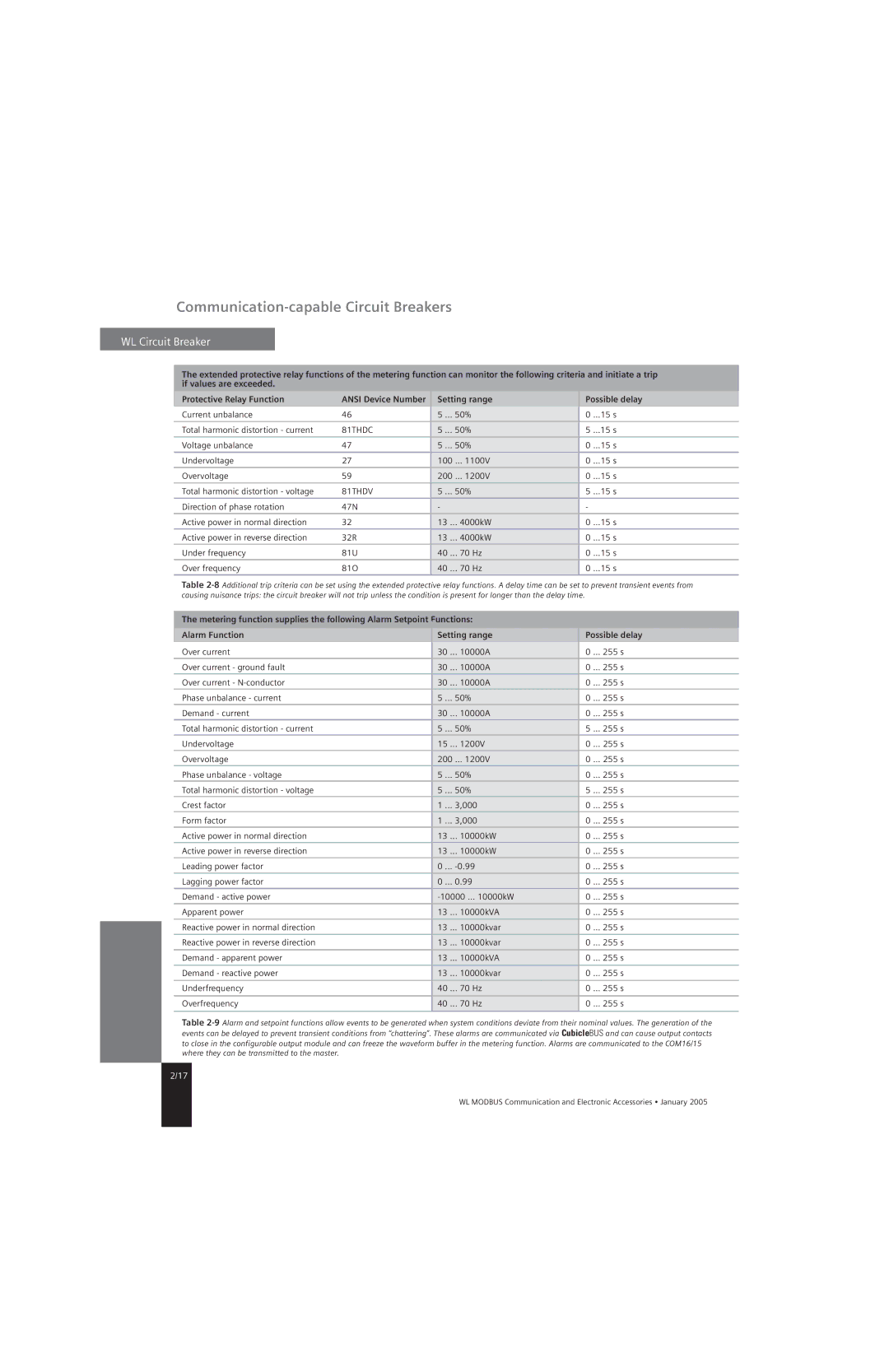
On the other hand, Siemens UL489 circuit breakers provide comprehensive protection against overcurrents and short circuits. These devices not only interrupt fault currents but also protect connected devices from damage due to overload situations. Key features of UL489 circuit breakers include adjustable trip settings, which allow users to customize the response to overcurrent conditions based on specific application requirements. This adaptability makes them suitable for a wide range of environments, from large industrial plants to smaller commercial buildings.
Both UL1066 and UL489 products are constructed with advanced technologies, such as thermal-magnetic or electronic trip mechanisms in UL489 devices, ensuring precise and timely interruption of fault currents. These technologies promote energy efficiency and stability within electrical systems. In addition, many of these devices are equipped with indication features, providing clear visual status cues for quick assessment in emergency situations.
In terms of characteristics, both UL1066 and UL489 devices adhere to rigorous testing and certification processes to meet UL standards. This compliance assures users of their performance and reliability. Furthermore, the devices are designed to accommodate a wide range of operating temperatures and environmental conditions, making them versatile choices for various applications.
In summary, Siemens UL1066 and UL489 devices are paramount in ensuring safety and efficiency in electrical circuits. Their advanced features and robust construction make them indispensable in protecting both personnel and equipment in an array of industrial and commercial applications.

