Communication-capable Circuit Breakers

WL Circuit Breaker

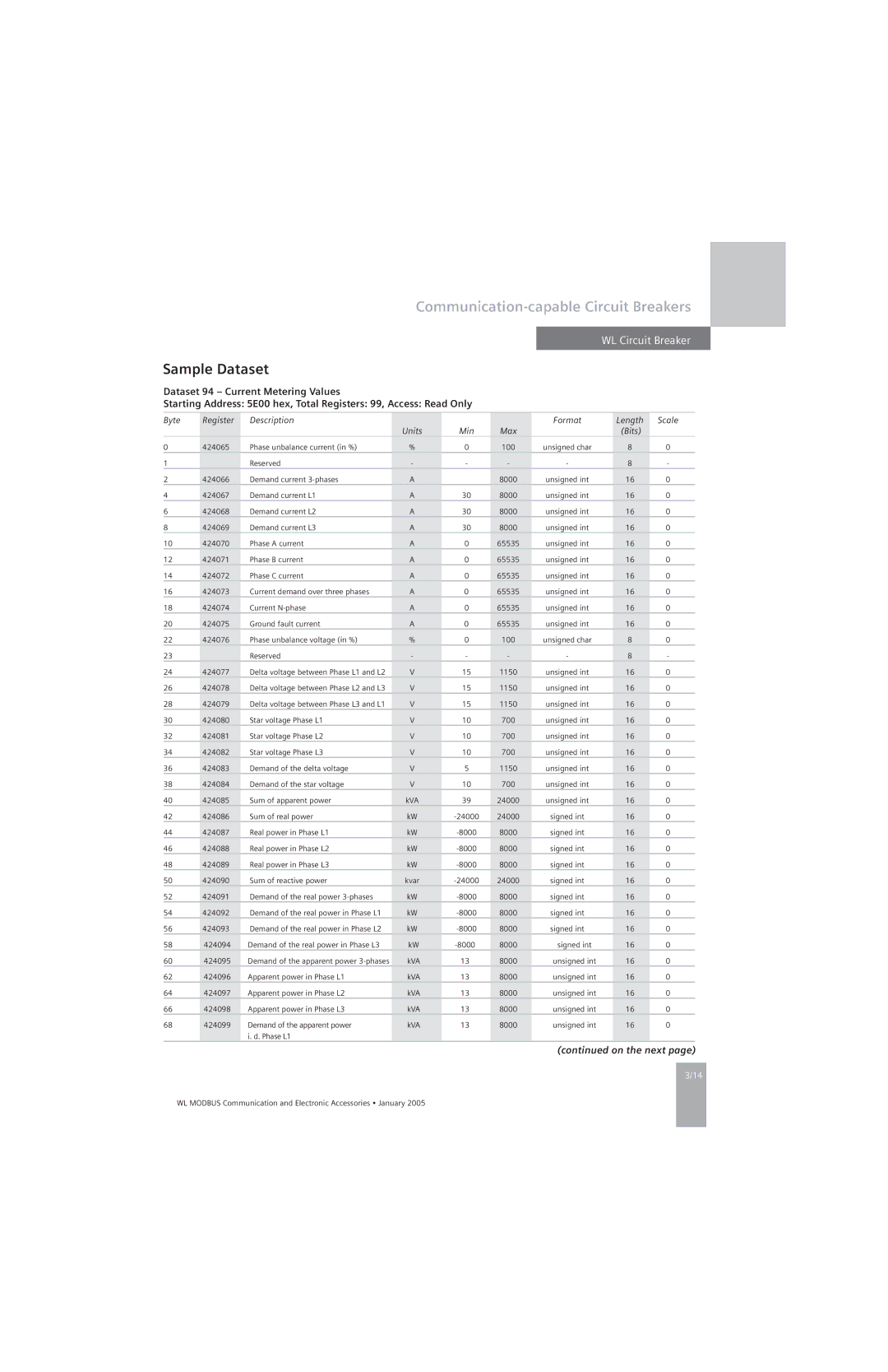
Sample Dataset

Dataset 94 – Current Metering Values

Starting Address: 5E00 hex, Total Registers: 99, Access: Read Only

Byte

Register

Description


Format

Length

Scale


Units

Min

Max


(Bits)


0

424065

Phase unbalance current (in %)

%

0

100

unsigned char

8

0

1


Reserved

-

-

-

-

8

-

2

424066

Demand current 3-phases

A


8000

unsigned int

16

0

4

424067

Demand current L1

A

30

8000

unsigned int

16

0

6

424068

Demand current L2

A

30

8000

unsigned int

16

0

8

424069

Demand current L3

A

30

8000

unsigned int

16

0

10

424070

Phase A current

A

0

65535

unsigned int

16

0

12

424071

Phase B current

A

0

65535

unsigned int

16

0

14

424072

Phase C current

A

0

65535

unsigned int

16

0

16

424073

Current demand over three phases

A

0

65535

unsigned int

16

0

18

424074

Current N-phase

A

0

65535

unsigned int

16

0

20

424075

Ground fault current

A

0

65535

unsigned int

16

0

22

424076

Phase unbalance voltage (in %)

%

0

100

unsigned char

8

0

23


Reserved

-

-

-

-

8

-

24

424077

Delta voltage between Phase L1 and L2

V

15

1150

unsigned int

16

0

26

424078

Delta voltage between Phase L2 and L3

V

15

1150

unsigned int

16

0

28

424079

Delta voltage between Phase L3 and L1

V

15

1150

unsigned int

16

0

30

424080

Star voltage Phase L1

V

10

700

unsigned int

16

0

32

424081

Star voltage Phase L2

V

10

700

unsigned int

16

0

34

424082

Star voltage Phase L3

V

10

700

unsigned int

16

0

36

424083

Demand of the delta voltage

V

5

1150

unsigned int

16

0

38

424084

Demand of the star voltage

V

10

700

unsigned int

16

0

40

424085

Sum of apparent power

kVA

39

24000

unsigned int

16

0

42

424086

Sum of real power

kW

-24000

24000

signed int

16

0

44

424087

Real power in Phase L1

kW

-8000

8000

signed int

16

0

46

424088

Real power in Phase L2

kW

-8000

8000

signed int

16

0

48

424089

Real power in Phase L3

kW

-8000

8000

signed int

16

0

50

424090

Sum of reactive power

kvar

-24000

24000

signed int

16

0

52

424091

Demand of the real power 3-phases

kW

-8000

8000

signed int

16

0

54

424092

Demand of the real power in Phase L1

kW

-8000

8000

signed int

16

0

56

424093

Demand of the real power in Phase L2

kW

-8000

8000

signed int

16

0

58

424094

Demand of the real power in Phase L3

kW

-8000

8000

signed int

16

0

60

424095

Demand of the apparent power 3-phases

kVA

13

8000

unsigned int

16

0

62

424096

Apparent power in Phase L1

kVA

13

8000

unsigned int

16

0

64

424097

Apparent power in Phase L2

kVA

13

8000

unsigned int

16

0

66

424098

Apparent power in Phase L3

kVA

13

8000

unsigned int

16

0

68

424099

Demand of the apparent power

kVA

13

8000

unsigned int

16

0


i. d. Phase L1


(continued on the next page)

3/14

WL MODBUS Communication and Electronic Accessories • January 2005

Page 61
Image 61
Siemens UL 489, UL1066 specifications Sample Dataset, Min Max Bits

UL 489, UL1066 specifications

Siemens UL1066 and UL489 are essential components in the landscape of electrical equipment, specifically in circuit protection and control. These standards ensure reliability, safety, and efficiency in various applications, including industrial, commercial, and residential settings.

The Siemens UL1066 is primarily focused on disconnect switches. These devices are designed to isolate electrical circuits, ensuring the safety of both personnel and equipment during maintenance or in case of faults. One of the key features of UL1066 disconnect switches is their high breaking capacity, enabling them to handle significant fault currents without failure. This characteristic is crucial in protecting downstream equipment from damage caused by short circuits. The UL1066 switches are also known for their robust construction, often featuring a metal enclosure that enhances durability and environmental resistance. Additionally, these switches can be operated manually or remotely, offering flexibility in operation and control.

On the other hand, Siemens UL489 circuit breakers provide comprehensive protection against overcurrents and short circuits. These devices not only interrupt fault currents but also protect connected devices from damage due to overload situations. Key features of UL489 circuit breakers include adjustable trip settings, which allow users to customize the response to overcurrent conditions based on specific application requirements. This adaptability makes them suitable for a wide range of environments, from large industrial plants to smaller commercial buildings.

Both UL1066 and UL489 products are constructed with advanced technologies, such as thermal-magnetic or electronic trip mechanisms in UL489 devices, ensuring precise and timely interruption of fault currents. These technologies promote energy efficiency and stability within electrical systems. In addition, many of these devices are equipped with indication features, providing clear visual status cues for quick assessment in emergency situations.

In terms of characteristics, both UL1066 and UL489 devices adhere to rigorous testing and certification processes to meet UL standards. This compliance assures users of their performance and reliability. Furthermore, the devices are designed to accommodate a wide range of operating temperatures and environmental conditions, making them versatile choices for various applications.

In summary, Siemens UL1066 and UL489 devices are paramount in ensuring safety and efficiency in electrical circuits. Their advanced features and robust construction make them indispensable in protecting both personnel and equipment in an array of industrial and commercial applications.