Communication-capable Circuit Breakers

WL Circuit Breaker

Testing the Digital Input and Output Modules

The test should be performed prior to any commissioning work to determine whether the circuit breaker and its components function properly.

The test mode can be used to check that the CubicleBUS modules function properly. A distinction must be made between the individual modules.

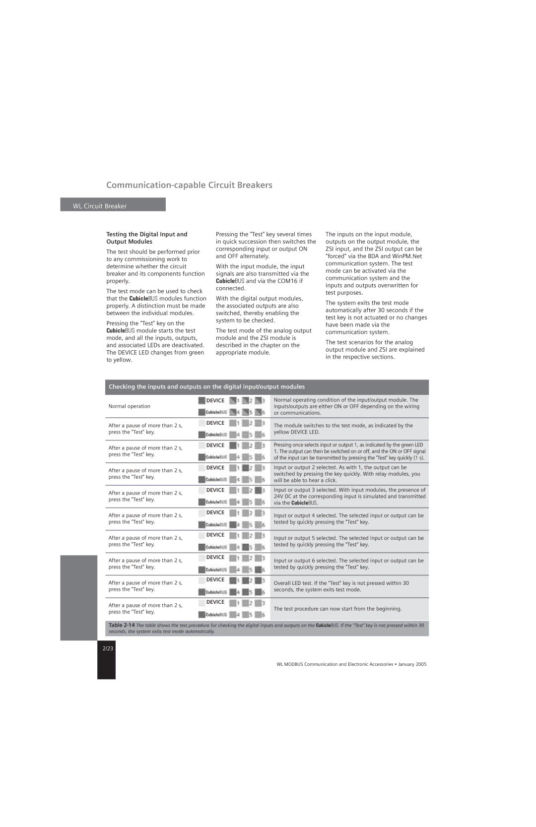
Pressing the "Test" key on the CubicleBUS module starts the test mode, and all the inputs, outputs, and associated LEDs are deactivated. The DEVICE LED changes from green to yellow.

Pressing the "Test" key several times in quick succession then switches the corresponding input or output ON and OFF alternately.

With the input module, the input signals are also transmitted via the CubicleBUS and via the COM16 if connected.

With the digital output modules, the associated outputs are also switched, thereby enabling the system to be checked.

The test mode of the analog output module and the ZSI module is described in the chapter on the appropriate module.

The inputs on the input module, outputs on the output module, the ZSI input, and the ZSI output can be "forced" via the BDA and WinPM.Net communication system. The test mode can be activated via the communication system and the inputs and outputs overwritten for test purposes.

The system exits the test mode automatically after 30 seconds if the test key is not actuated or no changes have been made via the communication system.

The test scenarios for the analog output module and ZSI are explained in the respective sections.

Checking the inputs and outputs on the digital input/output modules

Normal operation

DEVICE

Normal operating condition of the input/output module. The


inputs/outputs are either ON or OFF depending on the wiring


or communications.


After a pause of more than 2 s,

DEVICE

The module switches to the test mode, as indicated by the


press the "Test" key.


yellow DEVICE LED.


After a pause of more than 2 s,

DEVICE

Pressing once selects input or output 1, as indicated by the green LED


1. The output can then be switched on or off, and the ON or OFF signal

press the "Test" key.


of the input can be transmitted by pressing the "Test" key quickly (1 s).


After a pause of more than 2 s,

DEVICE

Input or output 2 selected. As with 1, the output can be


switched by pressing the key quickly. With relay modules, you

press the "Test" key.


will be able to hear a click.


After a pause of more than 2 s,

DEVICE

Input or output 3 selected. With input modules, the presence of


24V DC at the corresponding input is simulated and transmitted

press the "Test" key.


via the CubicleBUS.


After a pause of more than 2 s,

DEVICE

Input or output 4 selected. The selected input or output can be


press the "Test" key.


tested by quickly pressing the "Test" key.


After a pause of more than 2 s,

DEVICE

Input or output 5 selected. The selected input or output can be


press the "Test" key.


tested by quickly pressing the "Test" key.


After a pause of more than 2 s,

DEVICE

Input or output 6 selected. The selected input or output can be


press the "Test" key.


tested by quickly pressing the "Test" key.


After a pause of more than 2 s,

DEVICE

Overall LED test. If the "Test" key is not pressed within 30


press the "Test" key.


seconds, the system exits test mode.

After a pause of more than 2 s, press the "Test" key.

DEVICE

The test procedure can now start from the beginning.

Table 2-14The table shows the test procedure for checking the digital inputs and outputs on the CubicleBUS. If the “Test” key is not pressed within 30 seconds, the system exits test mode automatically.

2/23

WL MODBUS Communication and Electronic Accessories • January 2005

Page 34
Image 34
Siemens UL1066, UL 489 specifications Testing the Digital Input and Output Modules, Device

UL 489, UL1066 specifications

Siemens UL1066 and UL489 are essential components in the landscape of electrical equipment, specifically in circuit protection and control. These standards ensure reliability, safety, and efficiency in various applications, including industrial, commercial, and residential settings.

The Siemens UL1066 is primarily focused on disconnect switches. These devices are designed to isolate electrical circuits, ensuring the safety of both personnel and equipment during maintenance or in case of faults. One of the key features of UL1066 disconnect switches is their high breaking capacity, enabling them to handle significant fault currents without failure. This characteristic is crucial in protecting downstream equipment from damage caused by short circuits. The UL1066 switches are also known for their robust construction, often featuring a metal enclosure that enhances durability and environmental resistance. Additionally, these switches can be operated manually or remotely, offering flexibility in operation and control.

On the other hand, Siemens UL489 circuit breakers provide comprehensive protection against overcurrents and short circuits. These devices not only interrupt fault currents but also protect connected devices from damage due to overload situations. Key features of UL489 circuit breakers include adjustable trip settings, which allow users to customize the response to overcurrent conditions based on specific application requirements. This adaptability makes them suitable for a wide range of environments, from large industrial plants to smaller commercial buildings.

Both UL1066 and UL489 products are constructed with advanced technologies, such as thermal-magnetic or electronic trip mechanisms in UL489 devices, ensuring precise and timely interruption of fault currents. These technologies promote energy efficiency and stability within electrical systems. In addition, many of these devices are equipped with indication features, providing clear visual status cues for quick assessment in emergency situations.

In terms of characteristics, both UL1066 and UL489 devices adhere to rigorous testing and certification processes to meet UL standards. This compliance assures users of their performance and reliability. Furthermore, the devices are designed to accommodate a wide range of operating temperatures and environmental conditions, making them versatile choices for various applications.

In summary, Siemens UL1066 and UL489 devices are paramount in ensuring safety and efficiency in electrical circuits. Their advanced features and robust construction make them indispensable in protecting both personnel and equipment in an array of industrial and commercial applications.