Safety Instructions (continued)
NOTE
•Wire as short as possible to avoid the affect of noise and surge.
•Never use in the presence of explosive gases.
•Do not use in an area where magnetic field is generated to avoid malfunction of sensor.
•Do not operate where the flow sensor is exposed to water.
•Do not use in an area containing oil or chemicals.
•Do not apply heat cycle to the flow sensor.
•Do not used in an area where surges are generated.
•Sensors are not equipped with surge protection against lightening.
•Do not use load generate surge voltage.
•Avoid foreign material such as wiring chips in the product.
•Avoid using sensors in an environment where the likelihood of splashing or spraying of water, chemicals, and oil to avoid failure and malfunction.
•Consider operating environment according to protection class.
•Do not mount the flow sensor where vibration (98m/s2 or less) and impact (490m/s2 or less) do not exist to avoid failure and malfunction.
•Operation under low temperature (5![]() or less) leads to cause damage or operation failure due to frozen moist in the fluid or air.
or less) leads to cause damage or operation failure due to frozen moist in the fluid or air.
•Do not short circuit the load.
•Supply power when there is no flow.
•The flow sensor is compulsory turned off for 3s after power supplied.
•Maintenance and inspection should be performed periodically.
•Analogue output may fluctuate by 2 to 3% for 10 minutes after supplying power to the flow sensor.
•Do not poke inside a piping port with a stick.
•A flow rate of the flow sensor, which has a restrictor, may change if the needle turns due to vibration.
•The accuracy may fluctuate by 2 to 3% if a customer removes or replaces piping by themselves.
•When the product is fixed with a screw using the through hole, please tighten it with a 0.3Nm ± 0.05 or less of tightening torque. (Excessive tightening may break the product.)
Names and Functions of Individual Parts
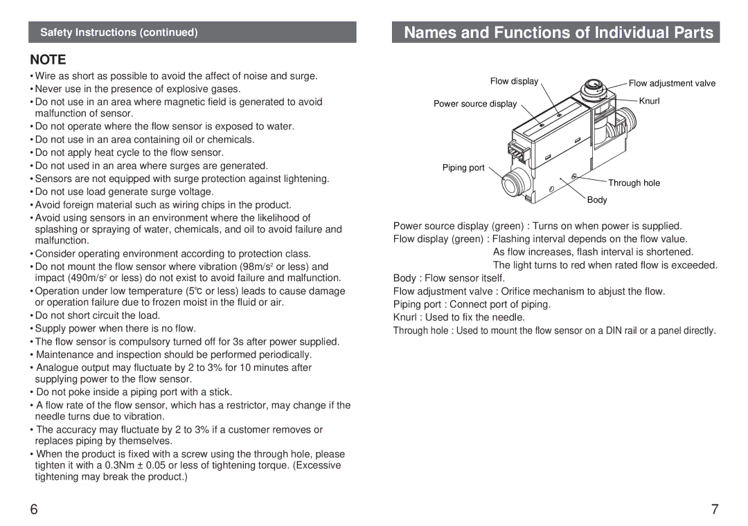
Flow display | Flow adjustment valve |
Power source display | Knurl |
|
Piping port
Through hole
Body
Power source display (green) : Turns on when power is supplied.
Flow display (green) : Flashing interval depends on the flow value. As flow increases, flash interval is shortened.
The light turns to red when rated flow is exceeded. Body : Flow sensor itself.
Flow adjustment valve : Orifice mechanism to abjust the flow.
Piping port : Connect port of piping.
Knurl : Used to fix the needle.
Through hole : Used to mount the flow sensor on a DIN rail or a panel directly.
6 | 7 |