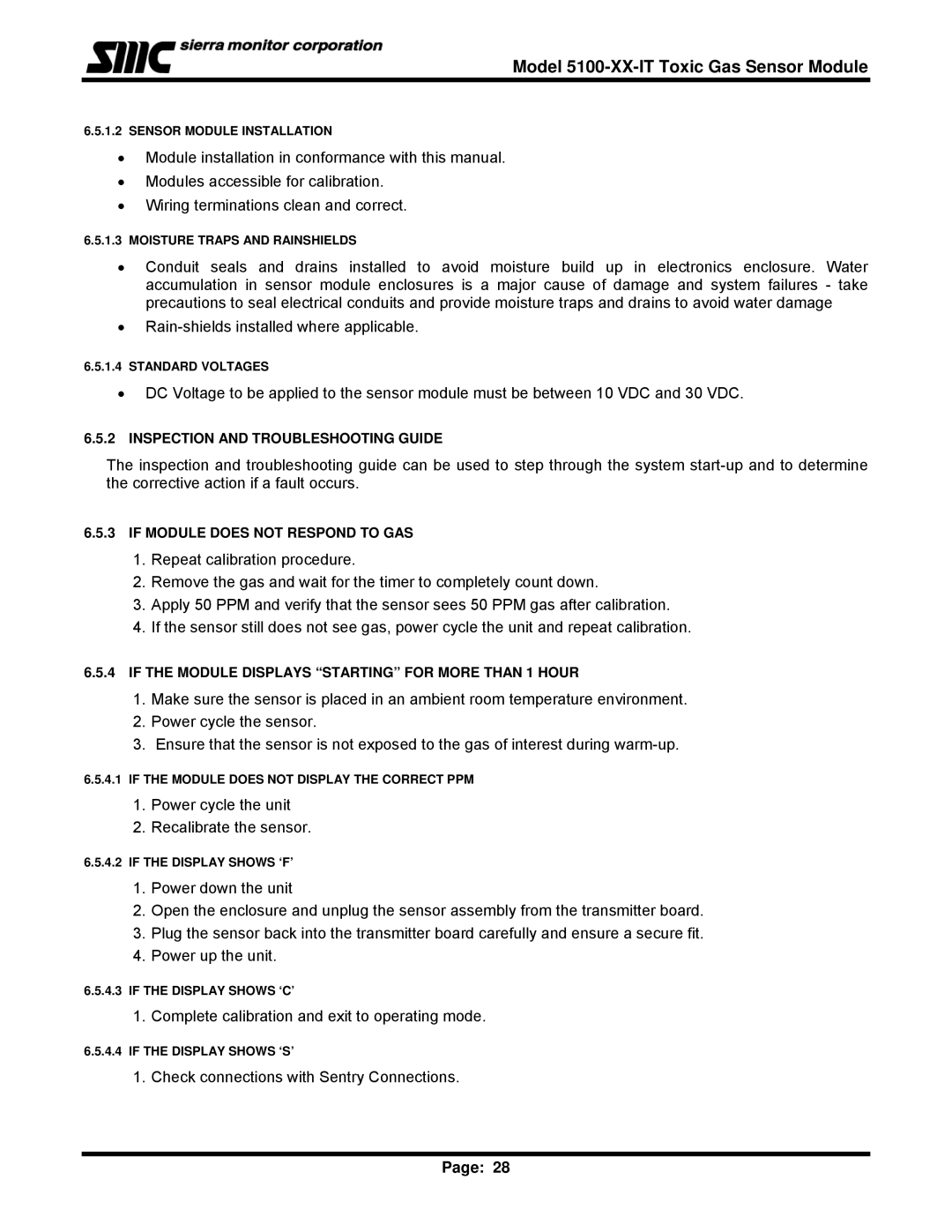
5100-03-IT, 5100-05-IT, 5100-06-IT, T12020, 5100-04-IT specifications
Sierra Monitor Corporation is renowned for its commitment to providing cutting-edge technology solutions for industrial monitoring and control systems. Among its notable products, the Sierra Monitor Corporation 5100 series, which includes models 5100-06-IT, 5100-05-IT, 5100-04-IT, and 5100-03-IT, stands out for its robust design and advanced features tailored for diverse applications in industrial environments. Additionally, the T12020 model complements this series, offering unique functionalities.The 5100 series is primarily designed for gas detection and monitoring, equipped with advanced sensors capable of identifying a wide array of gases, including combustible, toxic, and refrigerant gases. These models utilize state-of-the-art technology, including electrochemical and infrared sensors, ensuring high sensitivity and accuracy in detecting hazardous gases. This is crucial for maintaining safety in industrial settings where exposure to harmful gases can pose significant risks to personnel and equipment.
One of the main features of the 5100 series is its versatility. Each model is equipped with customizable settings, allowing users to configure alarm levels and response options to meet specific operational needs. This flexibility is essential in applications ranging from petrochemical plants to wastewater treatment facilities. The intuitive interface provides easy navigation and management, enabling users to monitor gas levels in real-time.
The 5100 series incorporates advanced communication technologies, including Modbus, RS-485, and Ethernet protocols. This facilitates seamless integration into existing control systems and enhances remote monitoring capabilities. Users can access real-time data and alarm notifications from any web-enabled device, ensuring prompt responses to potential gas leaks.
In addition to the 5100 series, the T12020 model serves as a robust solution for environmental and indoor air quality monitoring. It features similar advanced sensor technologies and offers additional applications, including HVAC control and indoor space safety management. This model provides essential data for building management systems, contributing to energy efficiency and improved air quality for occupants.
Overall, the Sierra Monitor Corporation’s 5100 series and the T12020 model exemplify the company’s dedication to innovation and safety. With a focus on reliability, precision, and user-friendly design, these products set a high standard in the field of gas detection and industrial monitoring, making a significant impact on enhancing workplace safety and operational efficiency.

