Assembly
Attaching Blade Guard
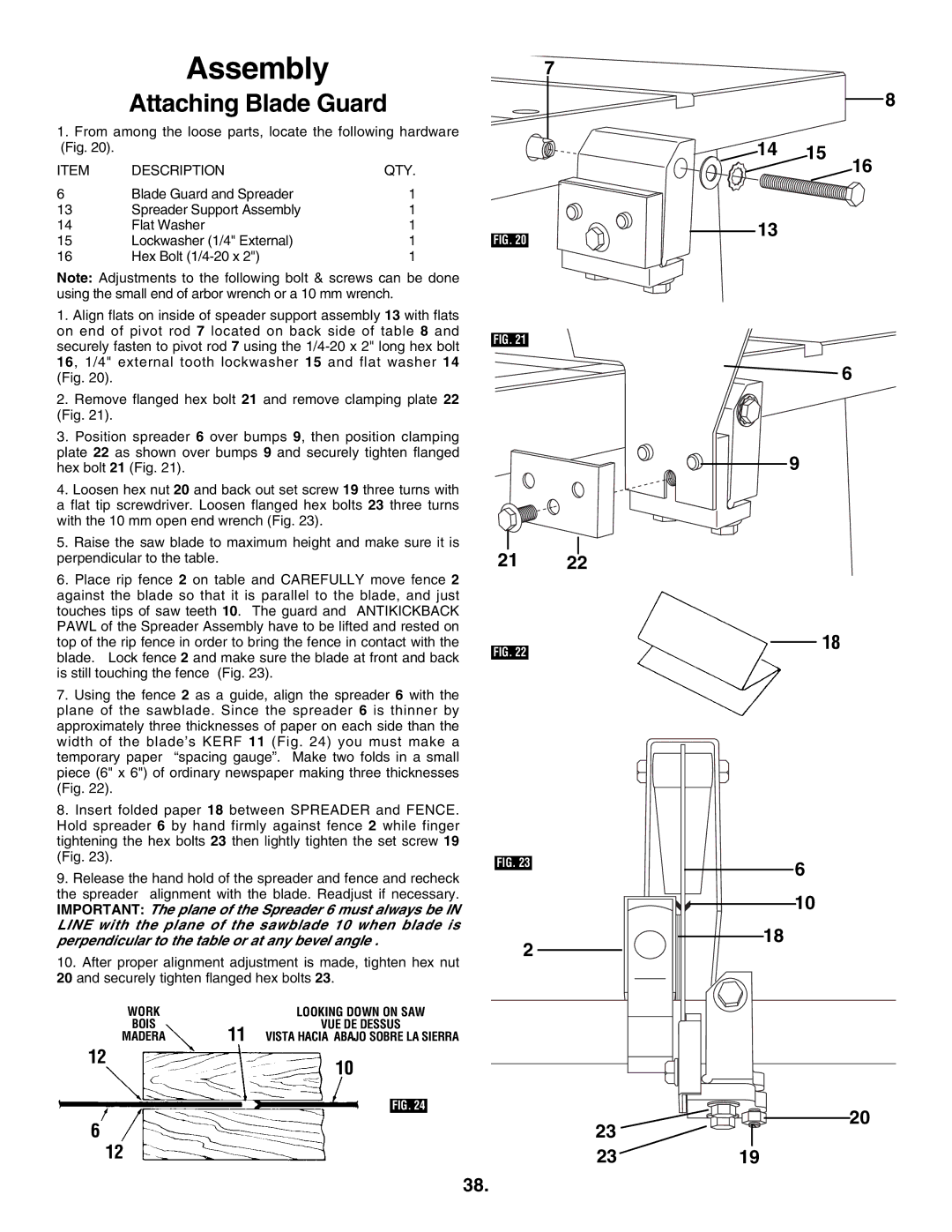
1.From among the loose parts, locate the following hardware (Fig. 20).
ITEM | DESCRIPTION | QTY. |
6 | Blade Guard and Spreader | 1 |
13 | Spreader Support Assembly | 1 |
14 | Flat Washer | 1 |
15 | Lockwasher (1/4" External) | 1 |
16 | Hex Bolt | 1 |
Note: Adjustments to the following bolt & screws can be done using the small end of arbor wrench or a 10 mm wrench.
1. Align flats on inside of speader support assembly 13 with flats |
on end of pivot rod 7 located on back side of table 8 and |
securely fasten to pivot rod 7 using the |
16, 1/4" external tooth lockwasher 15 and flat washer 14 |
7
FIG. 20
FIG. 21
14 15
13
8
16
(Fig. 20). |
2. Remove flanged hex bolt 21 and remove clamping plate 22 |
(Fig. 21). |
3. Position spreader 6 over bumps 9, then position clamping |
plate 22 as shown over bumps 9 and securely tighten flanged |
hex bolt 21 (Fig. 21). |
4. Loosen hex nut 20 and back out set screw 19 three turns with |
a flat tip screwdriver. Loosen flanged hex bolts 23 three turns |
with the 10 mm open end wrench (Fig. 23). |
5. Raise the saw blade to maximum height and make sure it is |
perpendicular to the table. |
6. Place rip fence 2 on table and CAREFULLY move fence 2 |
against the blade so that it is parallel to the blade, and just |
touches tips of saw teeth 10. The guard and ANTIKICKBACK |
PAWL of the Spreader Assembly have to be lifted and rested on |
top of the rip fence in order to bring the fence in contact with the |
blade. Lock fence 2 and make sure the blade at front and back |
is still touching the fence (Fig. 23). |
7. Using the fence 2 as a guide, align the spreader 6 with the |
plane of the sawblade. Since the spreader 6 is thinner by |
approximately three thicknesses of paper on each side than the |
width of the blade’s KERF 11 (Fig. 24) you must make a |
temporary paper “spacing gauge”. Make two folds in a small |
piece (6" x 6") of ordinary newspaper making three thicknesses |
(Fig. 22). |
8. Insert folded paper 18 between SPREADER and FENCE. |
Hold spreader 6 by hand firmly against fence 2 while finger |
tightening the hex bolts 23 then lightly tighten the set screw 19 |
(Fig. 23). |
9. Release the hand hold of the spreader and fence and recheck |
the spreader alignment with the blade. Readjust if necessary. |
IMPORTANT: The plane of the Spreader 6 must always be IN |
LINE with the plane of the sawblade 10 when blade is |
perpendicular to the table or at any bevel angle . |
10. After proper alignment adjustment is made, tighten hex nut |
20 and securely tighten flanged hex bolts 23. |
WORK |
| LOOKING DOWN ON SAW |
BOIS | 11 | VUE DE DESSUS |
MADERA | VISTA HACIA ABAJO SOBRE LA SIERRA |
12 | 10 |
| |
|
|
| |
|
|
|
|
|
|
| FIG. 24 |
6 |
|
|
|
| 12 |
|
|
21 22
FIG. 22
FIG. 23
2
23
23
![]() 6
6
9
18
6 |
10 |
18 |
20
19
38.