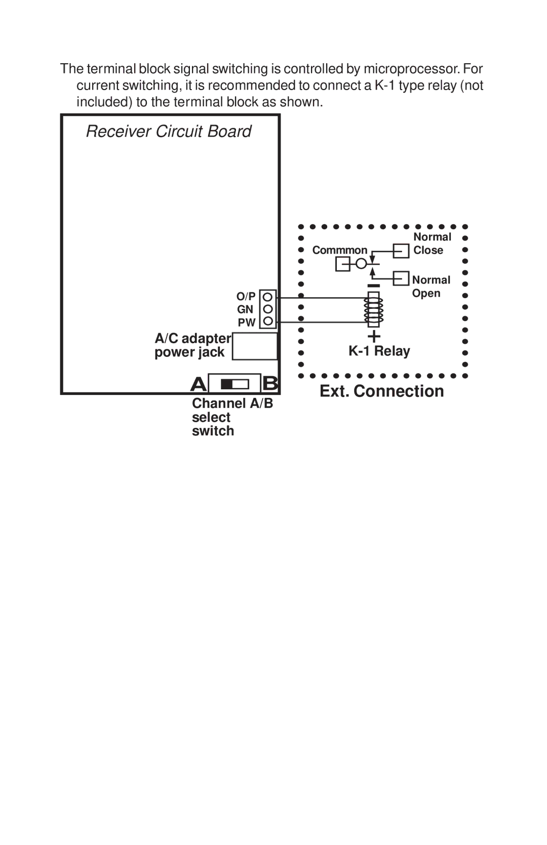
The terminal block signal switching is controlled by microprocessor. For current switching, it is recommended to connect a
Receiver Circuit Board
O/P
GN
PW
A/C adapter power jack
A![]()
![]()
![]()
![]() B
B
Channel A/B select switch
Normal
Commmon ![]()
![]() Close
Close
-![]()
![]() Normal Open
Normal Open
+