CABLES
Console Port Pin Assignments
The
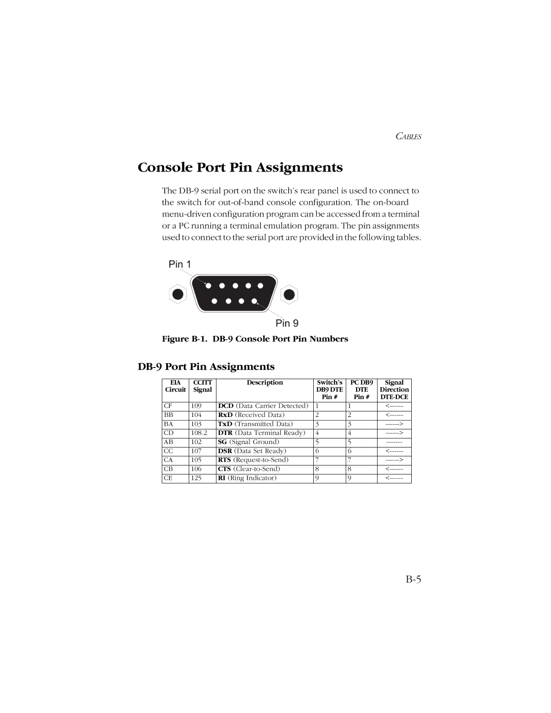
Figure B-1. DB-9 Console Port Pin Numbers
DB-9 Port Pin Assignments
EIA | CCITT | Description | Switch’s | PC DB9 | Signal |
Circuit | Signal |
| DB9 DTE | DTE | Direction |
|
|
| Pin # | Pin # | |
CF | 109 | DCD (Data Carrier Detected) | 1 | 1 | |
|
|
|
|
|
|
BB | 104 | RxD (Received Data) | 2 | 2 | |
BA | 103 | TxD (Transmitted Data) | 3 | 3 | |
CD | 108.2 | DTR (Data Terminal Ready) | 4 | 4 | |
|
|
|
|
|
|
AB | 102 | SG (Signal Ground) | 5 | 5 | |
CC | 107 | DSR (Data Set Ready) | 6 | 6 | |
CA | 105 | RTS | 7 | 7 | |
|
|
|
|
|
|
CB | 106 | CTS | 8 | 8 | |
CE | 125 | RI (Ring Indicator) | 9 | 9 |