Installation with a Tiller
|
|
| I |
|
|
| H |
|
|
|
|
|
| G |
|
|
|
| F |
|
|
| D | E |
| B | C |
| |
A |
|
| ||
|
|
| ||
|
|
|
|
| C |
| B |
A | D |
|
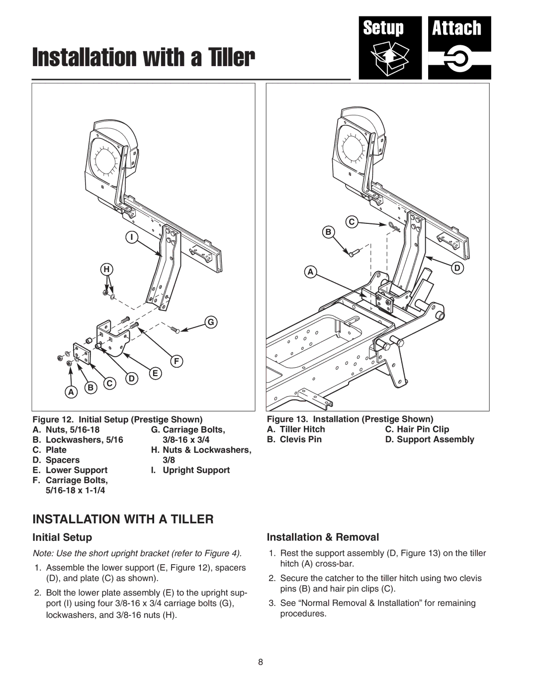
Figure 12. Initial Setup (Prestige Shown) | Figure 13. Installation (Prestige Shown) | ||
A. Nuts, | G. Carriage Bolts, | A. Tiller Hitch | C. Hair Pin Clip |
B. Lockwashers, 5/16 | B. Clevis Pin | D. Support Assembly | |
C. Plate | H. Nuts & Lockwashers, |
|
|
D. Spacers | 3/8 |
|
|
E. Lower Support | I. Upright Support |
|
|
F.Carriage Bolts,
INSTALLATION WITH A TILLER
Initial Setup
Note: Use the short upright bracket (refer to Figure 4).
1.Assemble the lower support (E, Figure 12), spacers (D), and plate (C) as shown).
2.Bolt the lower plate assembly (E) to the upright sup- port (I) using four
Installation & Removal
1.Rest the support assembly (D, Figure 13) on the tiller hitch (A)
2.Secure the catcher to the tiller hitch using two clevis pins (B) and hair pin clips (C).
3.See “Normal Removal & Installation” for remaining procedures.
8