Manuals
/
Heat & Glo LifeStyle
/
Household Appliance
/
Indoor Fireplace
Heat & Glo LifeStyle
SLR32 Appliance Setup, A. Remove Fixed Glass Assembly, D. Accessories
Models:
SLR32
1
56
70
70
Download
70 pages
24.45 Kb
53
54
55
56
57
58
59
60
Troubleshooting
Install
FAQ
E. Vent Diagrams
A. Wiring Requirements
Warranty
Dimension
Maintenance
Symptom
D. Accessories
Page 56
Image 56
Page 55
Page 57
Page 56
Image 56
Page 55
Page 57
Contents
NOTICE
Model SLR32
•What to do if you smell gas
Owner’s Manual
A. Congratulations
Homeowner Reference Information
Table of Contents
Safety Alert Key
Installer Guide
3 Maintenance and Service
14 Appliance Setup
15 Troubleshooting
= Contains updated information
13 Finishing
B. Limited Lifetime Warranty
LIMITED LIFETIME WARRANTY
WARRANTY COVERAGE
WARRANTY PERIOD
B. Limited Lifetime Warranty continued
WARRANTY CONDITIONS
WARRANTY EXCLUSIONS
This warranty is void if
D. High Altitude Installations
1 Listing and Code Approvals
A. Appliance Certification
B. Tempered Glass Specifications
Installation of Carbon Monoxide Detectors
A. Gas Fireplace Safety
2 Operating Instructions User Guide
B. Your Fireplace
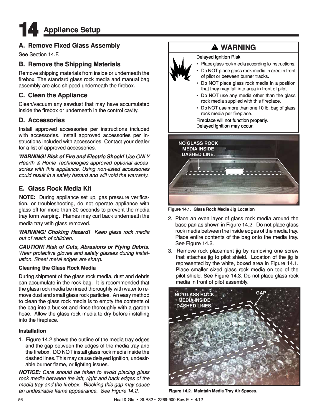
WARNING! Choking Hazard! Keep glass rock media
E. Fixed Glass Assembly
C. Clear Space
D. Decorative Doors and Fronts
G. Before Lighting Fireplace
H. Lighting Instructions IPI
Final inspection by
FOR YOUR SAFETY READ BEFORE LIGHTING
LIGHTING INSTRUCTIONS IPI
J. Frequently Asked Questions
I. After Fireplace is Lit
Initial Break-inProcedure
•Some people may be sensitive to smoke and odors
3 Maintenance and Service
A. Maintenance Tasks-Homeowner
Glass Cleaning
Remote Control
B.Maintenance Tasks-QualifiedService Technician
Gasket Seal and Glass Assembly Inspection
Venting
Firebox
Getting Started
A. Typical Appliance System
Installer Guide
WALL SWITCH
D. Inspect Appliance and Components
B. Design and Installation Considerations
C. Tools and Supplies Needed
5 Framing and Clearances
A. Selecting Appliance Location
B. Constructing the Appliance Chase
Heat & Glo • SLR32 • 2269-900Rev. E • 4/12
C. Clearances
MINIMUM FRAMING DIMENSIONS
D. Mantel and Wall Projections
Combustible Mantels
Non-combustibleMantels
Front Side Finishing Detail
Figure 5.8 Non-CombustibleZone
5 IN
WALL
SHEATHING
6 Termination Locations
A. Vent Termination Minimum Clearances
V= VENT TERMINAL X = AIR SUPPLY INLET
= AREA WHERE TERMINAL IS NOT PERMITTED
Covered Alcove Applications
7 Vent Information and Diagrams
E. Vent Diagrams
A. Approved Pipe
B. Vent Table Key
Top Vent - Horizontal Termination
Venting with 1 elbow
1. Top Vent - Horizontal Termination - continued
Venting with 2 elbows
INSTALLED HORIZONTALLY
Top Vent - Horizontal Termination
1. Top Vent - Horizontal Termination - continued
Top Vent - Horizontal Termination
Venting with 3 elbows
H2 V2 H1
Top Vent - Vertical Termination No Elbows
V1 = 44 ft. Max. 13.4 m
Exhaust restrictor Instructions
PILOT HOLES
Top Vent - Vertical Termination
Venting with 2 elbows
SLR32
V1 Minimum
Venting with 3 elbows
Top Vent - Vertical Termination
SLR32
V1 Minimum
Venting with 4 elbows
Top Vent - Vertical Termination
V3 H2 H1 V1
V1 MIN
Coaxial to Colinear Venting
Prior to installing the gas appliance
Table
Clearances to Combustibles
•Use separate vent system for this appliance
TOP VENT
•Vent this appliance directly outside
8 Vent Clearances and Framing
A. Pipe Clearances to Combustibles
B. Wall Penetration Framing
Between ceiling firestops
C. Install the Ceiling Firestop
Vaulted Ceiling Installation
D. Install Attic Insulation Shield
Flat Ceiling Installation
9 Appliance Preparation
A. Preparing Elbow Heat Shield
B. Securing and Leveling the Appliance
WARNING! Risk of Fire! Prevent contact with
•Sagging or loose insulation
•Insulation backing or plastic
10 Installing Vent Pipe SLP Pipe
A. Assemble Vent Sections
Pilot hole
B. Assemble Slip Sections
C. Secure The Vent Sections
E. Install Decorative Ceiling Components
D. Disassemble Vent Sections
CAULK
F. Install Metal Roof Flashing
G. Assemble and Install Storm Collar
H. Install Vertical Termination Cap
I. Install Decorative Wall Components
Figure
Figure 10.16 Wall Thimble
K. Install Horizontal Termination Cap
Figure 10.17 Venting through the wall
11 Gas Information
A. Fuel Conversion
B. Gas Pressure
Access Through the Valve Assembly
C. Gas Connection
D. High Altitude Installations
Valve Pressure Taps
•Ensure adequate ventilation
A. Wiring Requirements
B. IntelliFire Ignition System Wiring
C. Optional Accessories Requirements
12 Electrical Information
D. Electrical Service and Repair
E. Junction Box Installation
13 Finishing
A. Framing and Finishing Instructions
Setting the Fireplace into the Framing
Finishing Instructions
Figure 13.3 Finishing Details
Heat & Glo • SLR32 • 2269-900Rev. E • 4/12
Painting
Wallboard Joint-CrackPrevention and Repair
Finish and Sealing Joints
Finishing Around Opening with Gypsum Wallboard
B. Mantel and Wall Projections
Combustible Mantel Legs Or Wall Projections
Extending Past The Face Of The Fireplace
Failure to comply could cause fire
0 - 1 inch thickness-OverlapFit Method
C. Facing Material
Non-CombustibleFinish Materials
Non-CombustibleFinish Materials
0 Inches to 4 Inches Thick-InsideFit Method
Non-CombustibleFinish Material 0-4Inches Thick
3/4 IN
D. Decorative Fronts
Table 1. Dimensions of Tonic Decorative Front
Table 1. Dimensions of Martini Decorative Front
Figure 13.14 Dimensions of Tonic Decorative Front
14 Appliance Setup
A. Remove Fixed Glass Assembly
C. Clean the Appliance
D. Accessories
• MEDIA-AMBER • MEDIA-BLACK • MEDIA-CLEAR
• MEDIA-COBALT • MEDIA-BK2-GEMS • MEDIA-WH2-GEMS
• MEDIA-STONES-2 • SLR32-LOGS • MEDIA-CL2-GEMS
• GLASS32-LINER
F. Fixed Glass Assembly
G. Install the Mesh
H. Air Shutter Setting
Removing Fixed Glass Assembly
15 Troubleshooting
A. IntelliFire Ignition System
Symptom
Possible Cause
IntelliFire Ignition System - continued
Symptom
Possible Cause
Corrective Action
A. Appliance Dimension Diagram
16 Reference Materials
N R Q S P
M K L J I Ø A B E F C D
B. Vent Components Diagrams
9 in
12-1/2in
2-3/4in
B. Vent Components Diagrams continued
Effective Height Length
SLP-45- 45 Elbow
SLP90- 90 Elbow
B. Vent Components Diagrams continued
SLK-SNKD
SLP-CCS-BK
SLP-TVHW
SLP-HRC-SS SLP-HRC-ZC-SS
HORIZONTAL TERMINATION CAP
COAXIAL to COLINEAR VENTING
B. Vent Components Diagrams continued
Optional Wire Harness
DESCRIPTION
C. Service Parts
at depot
SLR32
Stocked
SLR32
at Depot
C. Service Parts
#11 Valve Assembly
SLR32
Stocked
C. Service Parts
at Depot
D. Contact Information
NOTICE
Top
Page
Image
Contents