250 Z & Javelin Series
Motion Control Lever
Adjustment
Operator Adjustment
The motion control levers can be adjusted in two ways. The placement of the levers (how close the ends are to one another) and the height of the levers can be adjust- ed.
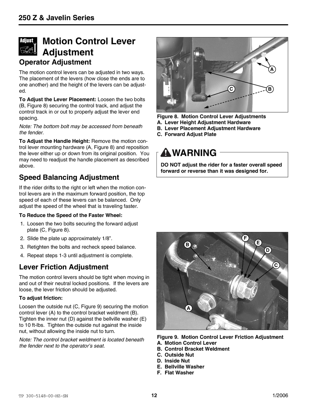
To Adjust the Lever Placement: Loosen the two bolts (B, Figure 8) securing the control track, and adjust the control track in or out to properly adjust the lever end spacing.
Note: The bottom bolt may be accessed from beneath the fender.
To Adjust the Handle Height: Remove the motion con- trol lever mounting hardware (A, Figure 8) and reposition the lever either up or down from its original position. You may need to readjust the handle placement as described above.
Speed Balancing Adjustment
If the rider drifts to the right or left when the motion con- trol levers are in the maximum forward position, the top speed of each of these levers can be balanced. Only adjust the speed of the wheel that is traveling faster.
To Reduce the Speed of the Faster Wheel:
A |
CB
Figure 8. Motion Control Lever Adjustments
A.Lever Height Adjustment Hardware
B.Lever Placement Adjustment Hardware
C.Forward Adjust Plate
![]()
![]() WARNING
WARNING
DO NOT adjust the rider for a faster overall speed forward or reverse than it was designed for.
1.Loosen the two bolts securing the forward adjust plate (C, Figure 8).
2.Slide the plate up approximately 1/8”.
3.Retighten the bolts and recheck speed balance.
4.Repeat steps
Lever Friction Adjustment
The motion control levers should be tight when moving in and out of their neutral locked positions. If the levers are loose, the lever friction should be adjusted.
To adjust friction:
Loosen the outside nut (C, Figure 9) securing the motion control lever (A) to the control bracket weldment (B). Tighten the inner nut (D) against the bellville washer (E) to 10
Note: The control bracket weldment is located beneath the fender next to the operator’s seat.
F
BE
D
C
A
Figure 9. Motion Control Lever Friction Adjustment
A.Motion Control Lever
B.Control Bracket Weldment
C.Outside Nut
D.Inside Nut
E.Bellville Washer
F.Flat Washer
TP | 12 | 1/2006 |