Troubleshooting, Adjustments, & Service
NEUTRAL ADJUSTMENTS
If the machine creeps while the motion control levers are locked into their neutral locked positions, then it may be necessary to adjust the link rods.
Perform this adjustment on a hard level surface such as a concrete floor.
IMPORTANT NOTE: This adjustment should be per- formed with the engine OFF. Perform the adjustment, then start the engine to check the adjustment. If further adjustment is required, stop the engine before perform- ing the adjustment.
1.Determine which wheel is creeping. The left side transmission and link rod control the left wheel, the right link rod controls the right wheel.
2.Disengage the PTO, lock the motion control levers into their neutral locked positions, turn the engine off, remove the key, and wait for all moving parts to stop.
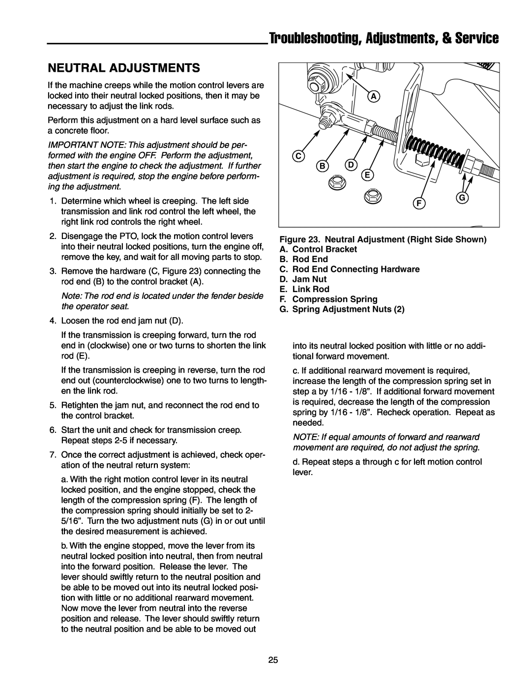
3.Remove the hardware (C, Figure 23) connecting the rod end (B) to the control bracket (A).
Note: The rod end is located under the fender beside the operator seat.
4.Loosen the rod end jam nut (D).
If the transmission is creeping forward, turn the rod end in (clockwise) one or two turns to shorten the link rod (E).
If the transmission is creeping in reverse, turn the rod end out (counterclockwise) one to two turns to length- en the link rod.
5.Retighten the jam nut, and reconnect the rod end to the control bracket.
6.Start the unit and check for transmission creep. Repeat steps
7.Once the correct adjustment is achieved, check oper- ation of the neutral return system:
a.With the right motion control lever in its neutral locked position, and the engine stopped, check the length of the compression spring (F). The length of the compression spring should initially be set to 2- 5/16”. Turn the two adjustment nuts (G) in or out until the desired measurement is achieved.
b.With the engine stopped, move the lever from its neutral locked position into neutral, then from neutral into the forward position. Release the lever. The lever should swiftly return to the neutral position and be able to be moved out into its neutral locked posi- tion with little or no additional rearward movement. Now move the lever from neutral into the reverse position and release. The lever should swiftly return to the neutral position and be able to be moved out
| A |
C | D |
B | |
| E |
| G |
| F |
Figure 23. Neutral Adjustment (Right Side Shown)
A.Control Bracket
B.Rod End
C.Rod End Connecting Hardware
D.Jam Nut
E.Link Rod
F.Compression Spring
G.Spring Adjustment Nuts (2)
into its neutral locked position with little or no addi- tional forward movement.
c. If additional rearward movement is required, increase the length of the compression spring set in step a by 1/16 - 1/8”. If additional forward movement is required, decrease the length of the compression spring by 1/16 - 1/8”. Recheck operation. Repeat as needed.
NOTE: If equal amounts of forward and rearward movement are required, do not adjust the spring.
d. Repeat steps a through c for left motion control lever.
25