4.Remove the
5.Remove the hairpin clips and washers (D, Figure 11) securing the rear mower deck brackets to the rear lift arm rod swivels, and pull the swivels out from the holes in the brackets. Retain all removed hardware.
6.Remove the hairpin clips and washers (A, Figure 12) securing the front mower deck brackets to the front lift arm rod swivels, and pull the swivels out from the holes in the brackets. Retain all removed hardware.
7.Pivot the front wheels out of the way and slide the mower deck out from under the unit.
Installation
1.Disengage the PTO, lock the motion control levers into their neutral lock positions, turn off the ignition, remove the key, and wait for all moving parts to stop.
2.Lower the height adjustment lever to its lowest posi- tion. See “CUTTING HEIGHT ADJUSTMENT”.
3.Pivot the front wheels out of the way and slide the mower deck under the unit. Place a 2 x 4 or similar support under each end of the mower deck.
4.Insert the front lift arm rod swivels into the holes in the front mower deck brackets, and secure each with a washer and hairpin clip (A, Figure 12).
5.Insert the rear lift arm rod swivels into the top holes in the rear mower deck brackets, and secure each with a washer and hairpin clip (D, Figure 11).
6.Install the rear end of each stabilizer bar (C, Figure 11) onto the mounting bolt on the transmission cas- ing, securing with a lock nut (B).
Note: Tighten the lock nuts only enough so that the stabilizer rods are snug but not tight.
Install the front end of each stabilizer rod out through the bottom holes of the rear mower deck brackets, and secure each with a washer and
7.Pull back on the tensioning idler (D, Figure 10) in the direction indicated, and install the belt onto the PTO pulley as shown in Figure 10.
Important: Be sure the belt is installed properly onto all pulleys.
| Operation |
D |
|
C | B |
| |
A |
|
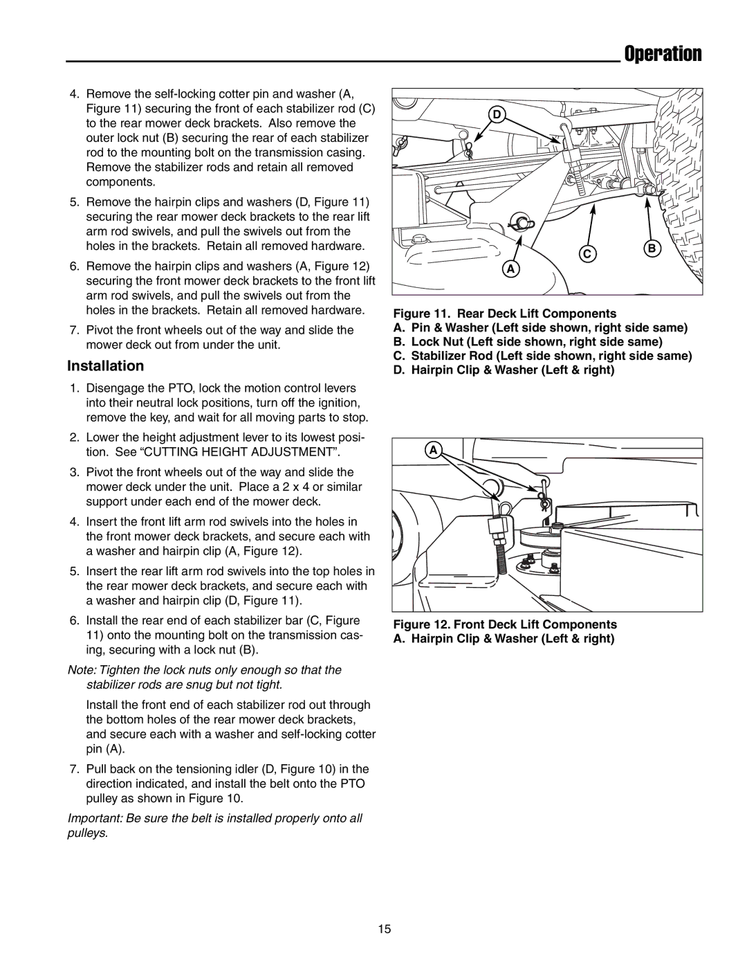
Figure 11. Rear Deck Lift Components
A.Pin & Washer (Left side shown, right side same)
B.Lock Nut (Left side shown, right side same)
C.Stabilizer Rod (Left side shown, right side same)
D.Hairpin Clip & Washer (Left & right)
A |
Figure 12. Front Deck Lift Components
A. Hairpin Clip & Washer (Left & right)
15