3 unit assembly (cont.)
TRANSMISSION SHIFT LEVER ASSEMBLY (cont.)
•Position
lever onto transmission stud, then slowly move handle of shifter back and forth until hole drops onto matching base of stud.
•Replace washer and nut onto transmission stud. Tighten securely. Replace lock nut onto
1/2” bolt. Tighten snugly while allowing for shifter movement.
• Work shift lever through gear range, adjusting indicator panel for display alignment, then tighten indicator panel hardware.
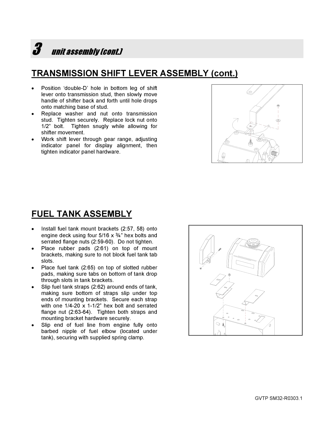
FUEL TANK ASSEMBLY
•Install fuel tank mount brackets (2:57, 58) onto engine deck using four 5/16 x ¾” hex bolts and serrated flange nuts
• Place rubber pads (2:61) on top of mount brackets, making sure to not block fuel tank tab slots.
•Place fuel tank (2:65) on top of slotted rubber pads, making sure tabs on bottom of tank drop through slots in tank brackets.
•Slip fuel tank straps (2:62) around ends of tank, making sure bottom of straps slip under top
ends of mounting brackets. Secure each strap with one
• Slip end of fuel line from engine fully onto barbed nipple of fuel elbow (located under tank), securing with supplied spring clamp.
GVTP