Sonance SM-Series instruction manual Introduction, Box Contents, Before Installation, A, C

Models: SM-Series

1 2
Download 2 pages 41.24 Kb
Page 1
Image 1
I N S T R U C T I O N M A N U A L

I N S T R U C T I O N M A N U A L

S M S E R I E S M O U N T I N G P L A T E

Introduction

Thank you for purchasing Sonance SM-Series Mounting Plates. This innovative mounting system eases installation by attaching directly to a J-Box in the ceiling, eliminating the need to cut a mounting hole for the speaker.

Box Contents

Item

Quantity (SM55 Plate)

SM Mounting Plates

2

Plastic terminal covers

2

(attached to the Mounting Plates)


1½” x 6-32 flat-head screws

4

Before Installation

1.Determine the location for the speaker (refer to the speak- er instruction manual for details).

2.The Mounting Plate installs onto a single or double J-box that has already been mounted on the wall or ceiling.

The Mounting Plate allows the speaker to be installed after the wall or ceiling has been finished.

Installation

1.Run speaker wires through the wall, ceiling or conduit, from the amplifier into the J-Box. Mark the wire’s “+” and “–” leads.

Consult local building codes before running speaker wires through walls or ceilings.

2.Bring the speaker wires through the J-Box and attach them to the binding posts on the back of the Mounting Plate. The SM55 Mounting Plates have two binding posts; the SM55SST Mounting Plates have four binding posts (see Figure 1). The binding posts will accept banana plugs or bare wire.

Quantity (SM55SST Plate) 1 1

2

Be sure to connect amplifier “+” to the Mounting Plate’s “+” terminal, and amplifier
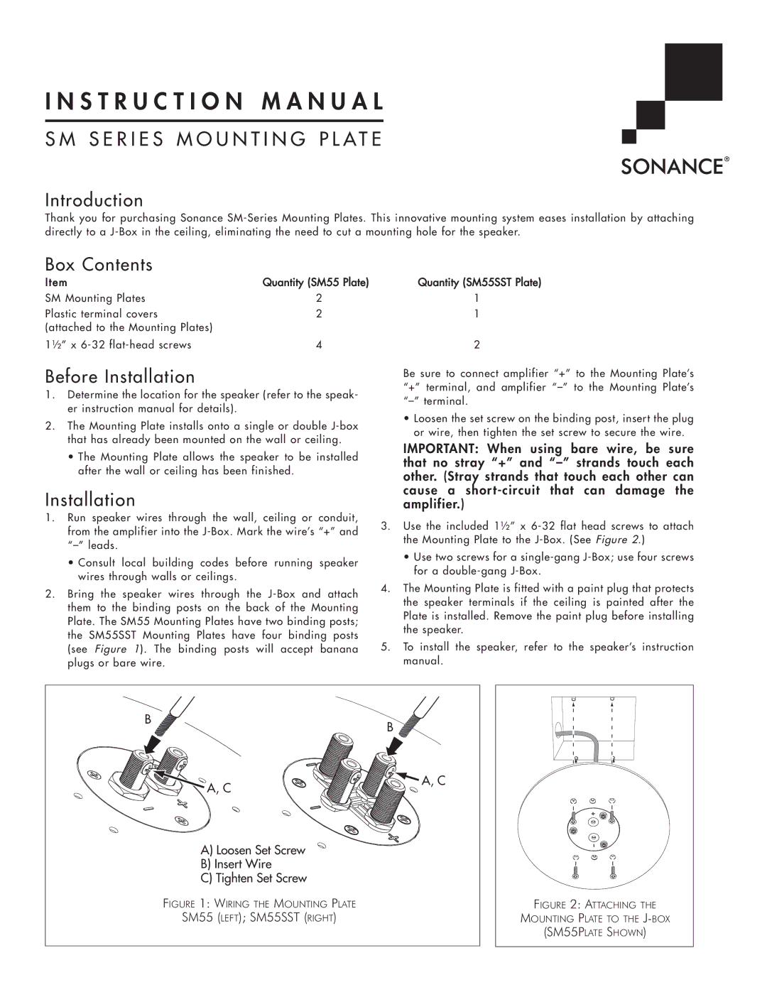
 “–” to the Mounting Plate’s “–” terminal.

Loosen the set screw on the binding post, insert the plug or wire, then tighten the set screw to secure the wire.

IMPORTANT: When using bare wire, be sure that no stray “+” and “–” strands touch each other. (Stray strands that touch each other can cause a short-circuit that can damage the amplifier.)

3.Use the included 1½” x 6-32 flat head screws to attach the Mounting Plate to the J-Box. (See Figure 2.)

Use two screws for a single-gang J-Box; use four screws for a double-gang J-Box.

4.The Mounting Plate is fitted with a paint plug that protects the speaker terminals if the ceiling is painted after the Plate is installed. Remove the paint plug before installing the speaker.

5.To install the speaker, refer to the speaker’s instruction manual.

B

B


A, C

A, C


A) Loosen Set Screw


B) Insert Wire


C) Tighten Set Screw


FIGURE 1: WIRING THE MOUNTING PLATE

FIGURE 2: ATTACHING THE

SM55 (LEFT); SM55SST (RIGHT)

MOUNTING PLATE TO THE J-BOX


(SM55PLATE SHOWN)

Page 1
Image 1
Sonance SM-Series instruction manual Introduction, Box Contents, Before Installation, I N S T R U C T I O N M A N U A L

FAQ

What are the box contents for Sonance SM-Series Mounting Plates?

The box includes 2 SM mounting plates, plastic terminal covers, and 1 x 6-32 flat-head screws.

How should I run speaker wires through the wall or ceiling?

Run speaker wires through the wall, ceiling, or conduit, and then bring the wires through the J-box and attach them to the binding posts on the back of the Mounting Plate.

What is the number of binding posts on SM55 Mounting Plates?

The SM55 Mounting Plates have two binding posts, while the SM55SST Mounting Plates have four binding posts.