Note: the video jack is for triggering purposes only; video signal switching is not possible.
External Voltage Trigger (Dip switch #2 On -- UP Position)
The B input relay may also be activated by a low voltage control source. This is by connecting a 5 to 24 Volts AC or DC power source to the screw terminal block on rear panel. This allows the ASAP2 to stay locked on the local source any time power is applied.
Typical applications would be:
•Control from switched outlet through a wall wart.
•DC Voltage output of preamp or control device.
•Relay drive output from out Navigator Master Keypad.
•Individual zone control such as Sonance Nav Net controller.
Caution: NEVER Connect to 120VAC line current.
AC Power Trigger (Dip switch #3 On -- UP Position)
The B input relay may also be activated by the AC power trigger. This is controlled by an AC outlet on rear panel which allows the ASAP2 to stay locked on to the local TV even when the audio signal is muted for an extended period of time. Plug your TV into this outlet, set trigger select DIP switch 2 to On position.
No Automatic Trigger (Dip switch #4 On -- UP Position)
This allows the ASAP2 to stay locked on to the local source bypassing all automatic functions. This application would be used when ASAP2 is in a switched outlet. When off, there would be direct pass through. When on, local ASAP2 inputs would be active. Pressing front panel power button would allow manual switching from Main to Local sources.
Time Delayed Input Muting (for AC Trigger Mode)
The ASAP2 mutes the input for 3 seconds to prevent thumps and pops created from low quality audio sources. (Typically television audio will produce audible thumps on the line out jacks). This application would be used when ASAP2 is in a the AC trigger mode.When off,there would be direct pass through. When TV is powered on, local ASAP2 inputs would be active and wait for 3 seconds for audio to pass. The muting is instant turn off, to catch quick off thump. This feature may be defeated if source equipment does not exhibit turn on /off thumps, or is using modes other than AC triggering.
Audio / Video Trigger Control Adjustment - Input Sensitivity
The ASAP2 can be adjusted for input sensitivity using the recessed screw adjustment labeled "sense" on the front panel. As it is turned clockwise, the sensitivity increases; counterclockwise makes it less sensitive. The unit should be set for the highest level of sensitivity that allows proper continuous operation. Operate the B source at a moderate volume, then mute the signal (if using a CD or tape player, put it in pause). The ASAP2 should switch back to the A source (after the time delay period you set above) and stay there. If the sensitivity is set too high, random switching may occur as the unit sense the residual noise level of the B source. Some experimentation may be necessary, but once it is set properly the ASAP2 will not need re-adjusting unless the components are changed.
AC Trigger Control Adjustment (front panel)
With TV or component on,adjust trigger control by using the recessed screw adjustment labeled "A.C. Trig" to the point of trigger. Then turn 1/8 past that setting. Check operation by switching TV or component on and off. If switching remains on, reduce the trigger setting slightly. Some components have a small change in current draw and may be
more difficult to trigger. In this case audio,video or low voltage may be an alternative option for better triggering stability.
Local to Main Delay Control Time Adjustment (front panel)
The ASAP2 features an adjustable time delay which varies the amount of time it takes for the device to revert to the A input after the B input signal has been discontinued. This delay time is set using the screw adjustment on the ASAP2 front panel labeled "Delay". The range is from 3 seconds (fully counterclockwise) to 90 seconds (fully clockwise). Set it for somewhat longer times if the video trigger is not used, or the local system is used for classical music or other sources containing long, quiet passages. If using audio for triggering, set the timing longer. If triggering other than audio, the delay time can be set to the shortest time setting (counterclockwise).
Local Source Volume Control Adjustment (front panel)
There are screw adjustments on the front panel for left and right volume control (marked "L" & "R") of local or internal power amplifier. Use these controls for the volume:
a. If the Local input signal is distorted or increase it if Local source has weak output. Typically TV variable output falls into the category.
b. If using a variable preamp/receiver output, leave them in the fully clockwise position.
c. If using ASAP2 with passive volume controls, set the passive volume control to maximum. Then adjust ASAP2 volume controls to nominal level without distortion.
AC Fuse
This will blow to protect the unit for possible internal parts failure. Never replace the fuse with any size other than indicated on the rear panel to avoid more serious damage. Substitution of a larger fuse may create serious damage to internal parts and will void your Sonance warranty. Note: For continued protection against fire, replace fuse with only same type and rating.
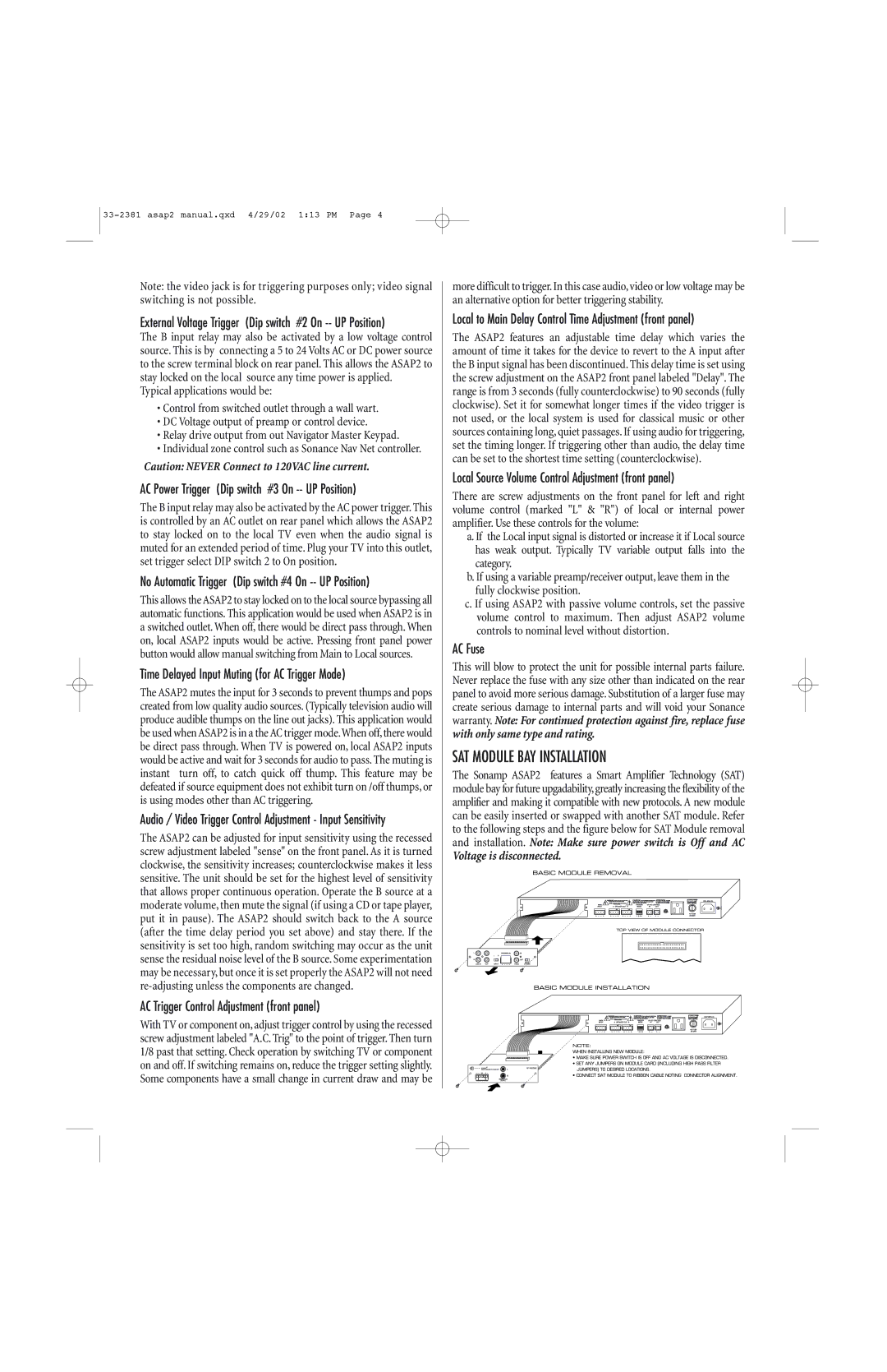
SAT MODULE BAY INSTALLATION
The Sonamp ASAP2 features a Smart Amplifier Technology (SAT) module bay for future upgadability,greatly increasing the flexibility of the amplifier and making it compatible with new protocols. A new module can be easily inserted or swapped with another SAT module. Refer to the following steps and the figure below for SAT Module removal and installation. Note: Make sure power switch is Off and AC
Voltage is disconnected.