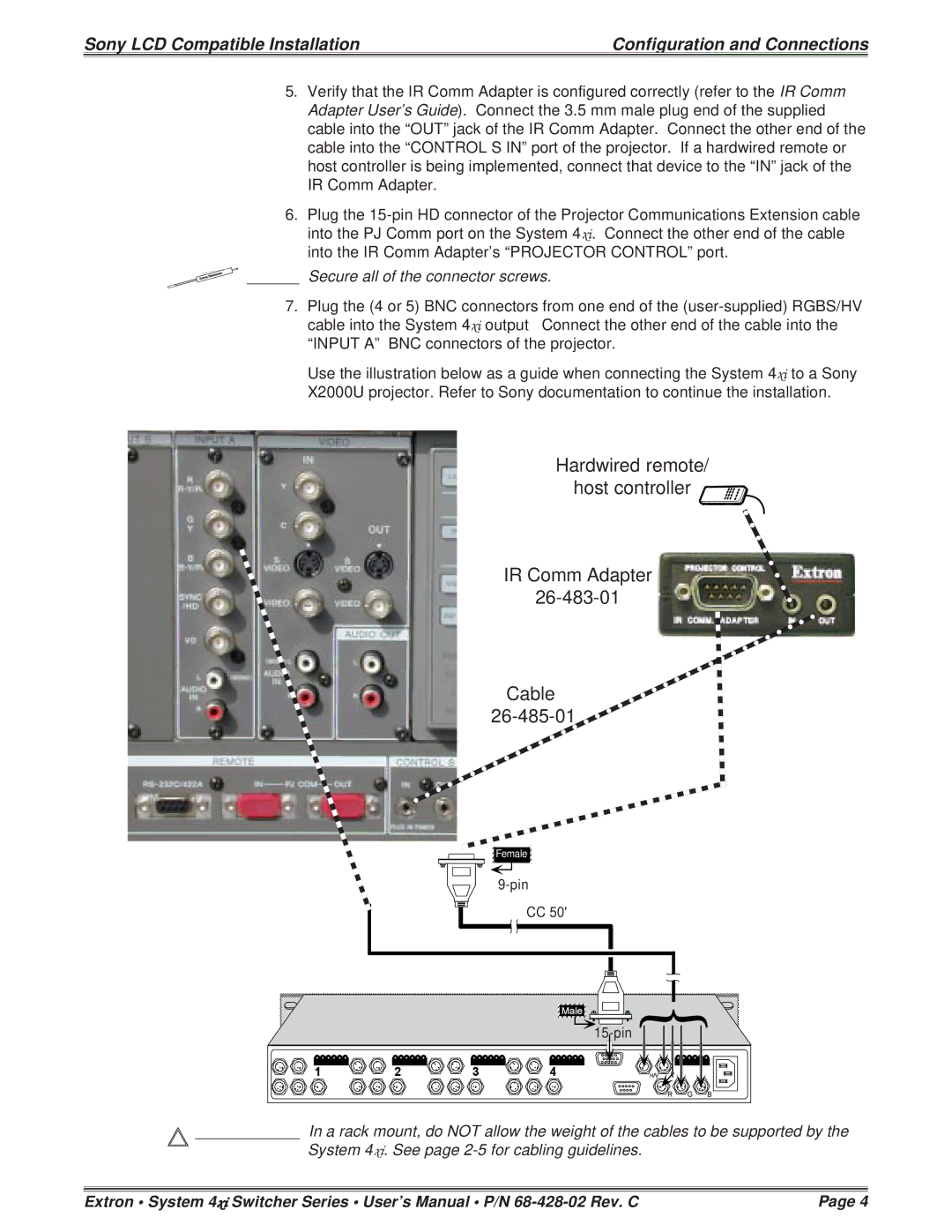
26-473-01, 26-483-01 specifications
The Sony 26-483-01 is a sophisticated piece of technology that showcases the brand's commitment to delivering high-performance products in the electronics landscape. This model is part of Sony’s extensive line of devices known for their innovative features and cutting-edge technologies, making it an attractive choice for consumers seeking quality and reliability.One of the standout features of the Sony 26-483-01 is its exceptional image quality. Equipped with advanced imaging technologies, the device provides stunning clarity and vibrancy, ensuring that every detail is captured with precision. The integration of HDR (High Dynamic Range) technology allows for a broader color gamut and enhanced contrast, resulting in images that are both lifelike and immersive. Whether being used for entertainment or professional purposes, users can expect a visually stunning experience.
In terms of connectivity, the Sony 26-483-01 does not disappoint. It includes multiple input options, enabling seamless integration with various devices, such as gaming consoles, Blu-ray players, and streaming devices. Additionally, built-in Wi-Fi capabilities allow for easy access to favorite streaming services, catering to the modern user's demand for convenience and flexibility. This connectivity is further enhanced by the inclusion of Bluetooth technology, enabling users to connect wireless headphones or speakers for a more personalized audio experience.
The design of the Sony 26-483-01 reflects a modern aesthetic fused with functional usability. Its sleek and compact form factor makes it an ideal addition to any setup, whether it be in a home, office, or entertainment space. The user-friendly interface ensures that even those who are not tech-savvy can navigate through settings and features effortlessly.
Another important aspect of the Sony 26-483-01 is its energy efficiency. With an emphasis on sustainability, the device is designed to consume less power while maintaining high performance, making it an environmentally-conscious choice. Users can enjoy high-quality performance without worrying about excessive energy consumption.
Overall, the Sony 26-483-01 is a stellar option for anyone looking to invest in a versatile, high-performance device. Its combination of advanced imaging capabilities, extensive connectivity options, stylish design, and energy-efficient operation positions it as a formidable contender in today’s technology-driven market. Whether for entertainment or professional use, the Sony 26-483-01 stands out as a reliable and innovative choice.

