Identifying the Parts
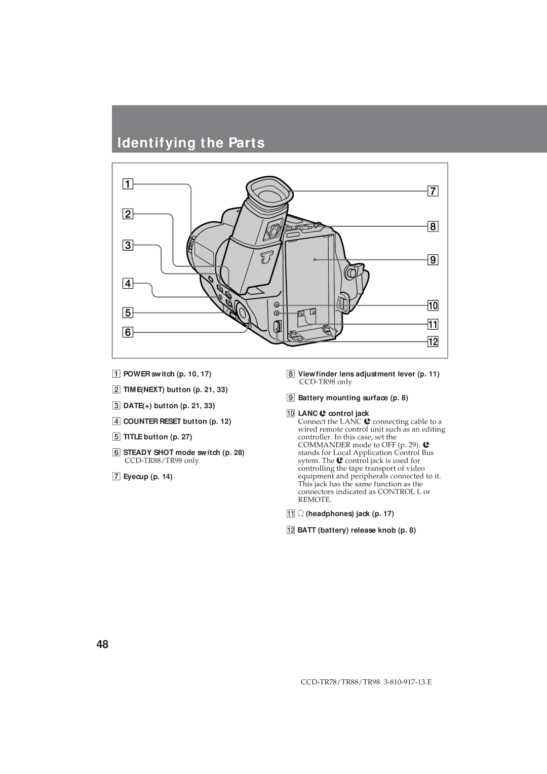
1 POWER switch (p. 10, 17) | 8 Viewfinder lens adjustment lever (p. 11) |
|
2TIME(NEXT) button (p. 21, 33)
3 DATE(+) button (p. 21, 33) | 9 Battery mounting surface (p. 8) | |
0 LANC l control jack | ||
| ||
4 COUNTER RESET button (p. 12) | Connect the LANC l connecting cable to a | |
5 TITLE button (p. 27) | wired remote control unit such as an editing | |
controller. In this case, set the | ||
6 STEADY SHOT mode switch (p. 28) | COMMANDER mode to OFF (p. 29). l | |
stands for Local Application Control Bus | ||
sytem. The l control jack is used for | ||
| controlling the tape transport of video | |
7 Eyecup (p. 14) | equipment and peripherals connected to it. | |
| This jack has the same function as the | |
| connectors indicated as CONTROL L or | |
| REMOTE. | |
| !Á 2 (headphones) jack (p. 17) | |
| !ª BATT (battery) release knob (p. 8) |
48