Please read the important safety information on page 2-EN
Color Rear Video Projector
Precaucion
Table of contents
Welcome!Precautions
Safety
Installing
About this manual
Installing the projection TV
Carrying your projection TV
Optimum viewing area Horizontal
Preparing for your projection TV
Hookup
Connecting an antenna/cable TV system without a VCR
Connecting an antenna
Connecting an antenna/cable TV system with a VCR
To a conventional VCR
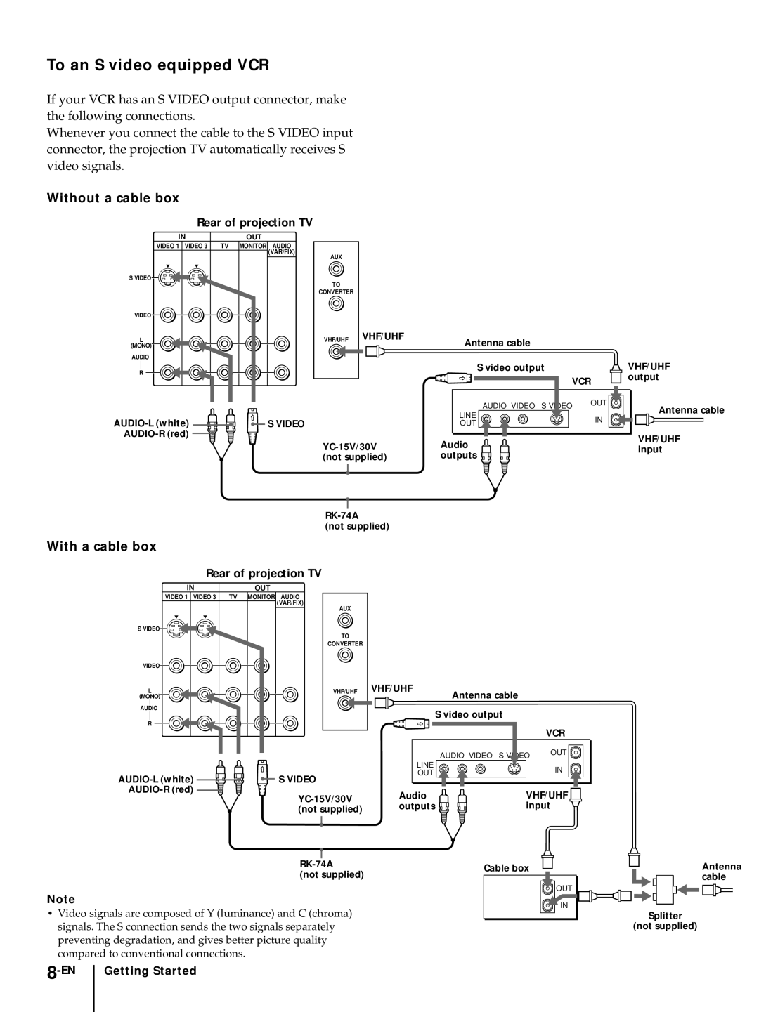
Without a cable box
With a cable box
To an S video equipped VCR
To a projection TV and VCR
Connecting a DBS receiver
To a projection TV
Connecting a camcorder
Connecting an audio system
Use this connection to view a camcorder picture
Front of projection TV
Connecting an AV receiver
Getting Started 11-EN
Connecting two VCRs for tape editing using Monitor OUT
Getting Started 13-EN
CR red CB blue Green
Connecting an amplifier with Dolby Pro Logic decoder
Getting Started 15-EN
Connecting a Sony Sava series speaker system
Getting Started 17-EN
Using the S-Link function
Using the S-Link function without a Sony AV receiver
Using the S-Link function with a Sony AV receiver
Connecting other Sony equipment with Control S jack
Getting Started 19-EN
Getting to know buttons on the remote control
Inserting batteries
Button color
Label color
Setting up the projection TV automatically
Auto SET UP
Erasing or adding channels
To preview the main functions Demo
Press TV Function
Press Menu
Adjusting convergence
Press Vor vto select Channel ERASE/ADD
Channel ERASE/ADD menu appears
Erase and/or add channels
Setting cable TV on or off
Getting Started 25-EN
Presetting channels
Press Vor vto select Press Vor vto select Auto PROGRAM,
Muting the sound
Switching quickly between two channels
Watching the TV
Setting the Sleep Timer
Displaying on-screen information
Watching a video input picture
Changing the VHF/UHF input to the AUX input
Changing the window/left picture input mode
Watching two programs at one time PIP/P&P
Displaying a left picture P&P
Displaying a window picture PIP
Listening to the sound of the window/ left picture
Swapping the main/right and window/ left pictures
Changing TV channels in the window/ left picture
Changing the position of the window picture
Freeze
Adjusting the picture Video
Freezing the picture
Adjusting the color temperature Trinitone
Adjust the selected item
To restore the factory settings
Press Vor vto select Ntsc STD, MEDIUM, or High and press
Adjusting
To adjust bass, press Vor vto move the cursor z to Bass
Selecting the video
32-EN Operations
Using audio effect
Using the audio effect button
Press New setting appears in the Audio menu
Effect
MTS
Using the menu to set audio effect
Selecting stereo or bilingual programs
Operations 35-EN
Setting the speaker
Press Vor vto select ON, OFF, Center or
Setting audio out
Setting daylight saving time Daylight
Audio OUT
Saving
Setting the clock Setting the timer to
ON/OFF Timer
Turn the projection
TV on and off
To cancel the timer
Customizing the channel names
Channel Caption
Press Vor vto select Channel CAPTION, and press
, press Reset
To cancel a Channel Block setting
Or 5, press Reset
Enter the letters up to four to caption the channel
Setting your favorite channels
Setting your favorite channels
Favorite Channel
Selecting your favorite channel
Setting video labels
Video Label
Press Vor vto select the label, and press
Each time you press Vor v, the label changes as follows
Setting Caption Operating video
Setting the manufacturer’s code
Equipment
Press Vor vto select CC , and press
VCR manufacturer code numbers
MDP manufacturer code numbers
DVD manufacturer code numbers
Operations 43-EN
Press System OFF
Operating video equipment
Turning off the system
Operating a cable box or DBS receiver
To operate the projection TV
For more details on operating the cable box or DBS receiver
Manufacturer code numbers cable box
Troubleshooting
Specifications
Index to parts and controls
Projection TV Front
Channel +/- buttons LMONO/R jacks
EN Additional Information
Remote control
Additional Information 49-EN
Names of controls
Index
DVD 13
Additional Information 51-EN
Registro del propietario
Nota sobre la visualización de subtítulos
Nota para el instalador del sistema de cable
Observación sobre el ajuste de convergencia
Cubierta posterior Indice
Indice
¡Bienvenido Precauciones
¡Bienvenido! Precauciones
Acerca de este manual
Seguridad
Instalación
Paso 1 Instalación del TV de proyección
Area de visualización óptima Horizontal
Transporte del TV de proyección
Preparativos para el TV de proyección
Conexión de una antena
Cable o antena
Decodificador
Decodificador y un sistema de cable
Una videograbadora convencional
Sin utilizar un decodificador
Con un decodificador
Parte posterior del TV de proyección
Una videograbadora provista de conector S vídeo
Un TV de proyección y una videograbadora
Conexión de un receptor DBS
Un TV de proyección
Conexión a cámara de vídeo
Conexión a un sistema de audio
Parte frontal del TV de proyección
10-ES Preparativos
Conexión de un receptor AV
Preparativos 11-ES
12-ES Preparativos
Preparativos 13-ES
14-ES Preparativos
Salidas de vídeo para componentes
Preparativos 15-ES
Conexión a un sistema de bocinas serie Sava de Sony
16-ES Preparativos
Preparativos 17-ES
Uso de la función S-Link
Uso de la función S-Link sin receptor AV de Sony
Uso de la función S-Link con un receptor AV de Sony
18-ES Preparativos
Conexión de otro equipo Sony provisto de la toma Control S
Preparativos 19-ES
Paso 3 Preparación del control remoto
Inserción de las pilas
Teclas del control remoto
Color de tecla
Paso 4 Ajuste del TV de proyección automáticamente
Auto Ajustes
Borrado o añadido de canales
Para ver las funciones principales Demo
Oprima TV Function
Oprima Menu
Borre y/o añada el canal que desee
Ajuste de la convergencia
Oprima Vo vpara seleccionar Borrar Añadir CANAL, y oprima
Activación y desactivación del modo de cable
Oprima Vo vpara seleccionar Ajuste Cable en SI o no
Para desplazarse Oprima
24-ES Preparativos
Preparativos 25-ES
Cambio del idioma de menú
Programación de canales
Eliminación del sonido
Visión de programas de televisión
Cambio rápido entre dos canales
Visualización de indicaciones en pantalla
Empleo del apagado automático
Visualización de la imagen de entrada de vídeo
Cambio de la entrada VHF/UHF a la entrada AUX
Visualización de dos programas a la vez
Visualización de una imagen izquierda P&P
Visualización de una imagen en ventana PIP
Oprima
Recepción del sonido de la imagen en ventana/izquierda
Cambio de la posición de la imagen en ventana
Congelación de la Ajuste de la imagen
Video
Ajuste de la temperatura de
Ajuste la opción seleccionada
Para restaurar los ajustes de fábrica
Oprima Vo vpara seleccionar Ntsc STD Medio o Alto y oprima
Selección del modo Ajuste del sonido De vídeo Video
Audio
Oprima Vo vpara seleccionar MODO, y
32-ES Operaciones
Efecto sonoro Efecto
Uso de la tecla de efecto sonoro
Oprima V, B, vo bpara ajustar la opción
Oprima El nuevo ajuste aparece en el menú Audio
Selección de programas en estéreo o bilingües
Uso del menú para ajustar el efecto sonoro
Oprima Vo vpara seleccionar EFECTO, y
Oprima Vo vpara seleccionar SRS, 3D MONO, o NO, y oprima
Selección de las
Operaciones 35-ES
Selección de salida Ajuste de la hora de De audio Salida
Oprima Vo vpara seleccionar Variable o FIJA, y oprima
Oprima Vo vpara seleccionar SI o NO, y
36-ES Operaciones
ENCENDIDO/APAGADO
Ajuste del reloj Fijar
Hora Actual
Para cancelar el temporizador
Personalización de los nombres de los
Canal
Oprima Menu Oprima Vo vpara seleccionar
Para cancelar un ajuste Bloquear Canal
Bloqueo de canales
Bloquear Canal
Para borrar un nombre
Ajuste de los canales preferidos
Canal Favorito
Programación de los canales preferidos
Selección de un canal preferido
Etiquetado de
Oprima Vo vpara seleccionar Etiqueta DE VIDEO, y oprima
Oprima Vo vpara seleccionar la etiqueta, y oprima
Operaciones 41-ES
Ajuste de subtítulos Uso de equipos de
Vídeo
Caption Vision
Ajuste del código de fabricante
Operaciones 43-ES
Uso de equipos de vídeo
Desactivación simultánea del sistema
Oprima System OFF
44-ES Operaciones
Uso de un decodificador o receptor DBS
Para utilizar el TV de proyección
Códigos de los fabricantes decodificador
Códigos de los fabricantes receptor DBS
Solución de problemas
Especificaciones
48-ES
Indice de partes y controles
Parte delantera del TV de proyección
Control remoto
49-ES
Nombre de los controles