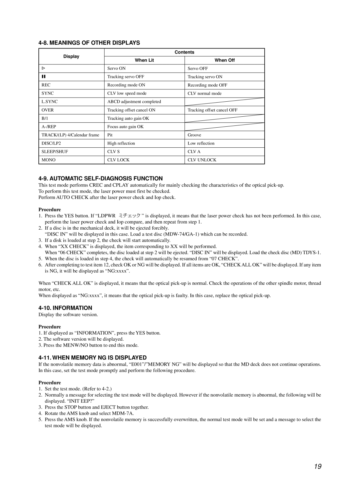
4-8. MEANINGS OF OTHER DISPLAYS
Display |
| Contents | |
|
|
| |
When Lit |
| When Off | |
|
| ||
|
|
|
|
G | Servo ON |
| Servo OFF |
|
|
|
|
X | Tracking servo OFF |
| Tracking servo ON |
|
|
|
|
REC | Recording mode ON |
| Recording mode OFF |
|
|
|
|
SYNC | CLV low speed mode |
| CLV normal mode |
|
|
|
|
L.SYNC | ABCD adjustment completed |
|
|
|
|
|
|
OVER | Tracking offset cancel ON |
| Tracking offset cancel OFF |
|
|
|
|
B/1 | Tracking auto gain OK |
|
|
|
|
|
|
Focus auto gain OK |
|
| |
|
|
|
|
TRACK/(LP) 4/Calendar frame | Pit |
| Groove |
|
|
|
|
DISC/LP2 | High reflection |
| Low reflection |
|
|
|
|
SLEEP/SHUF | CLV S |
| CLV A |
|
|
|
|
MONO | CLV LOCK |
| CLV UNLOCK |
|
|
|
|
4-9. AUTOMATIC SELF-DIAGNOSIS FUNCTION
This test mode performs CREC and CPLAY automatically for mainly checking the characteristics of the optical
Perform AUTO CHECK after the laser power check and Iop check.
Procedure
1.Press the YES button. If “LDPWR ![]()
![]()
![]()
![]() ” is displayed, it means that the laser power check has not been performed. In this case, perform the laser power check and Iop compare, and then repeat from step 1.
” is displayed, it means that the laser power check has not been performed. In this case, perform the laser power check and Iop compare, and then repeat from step 1.
2.If a disc is in the mechanical deck, it will be ejected forcibly.
“DISC IN” will be displayed in this case. Load a test disc
3.If a disk is loaded at step 2, the check will start automatically.
4.When “XX CHECK” is displayed, the item corresponding to XX will be performed.
When “06 CHECK” completes, the disc loaded at step 2 will be ejected. “DISC IN” will be displayed. Load the check disc (MD)
5.When the disc is loaded in step 4, the check will automatically be resumed from “07 CHECK”.
6.After completing to test item 12, check OK or NG will be displayed. If all items are OK, “CHECK ALL OK” will be displayed. If any item is NG, it will be displayed as “NG:xxxx”.
When “CHECK ALL OK” is displayed, it means that the optical
When displayed as “NG:xxxx”, it means that the optical
4-10. INFORMATION
Display the software version.
Procedure
1.If displayed as “INFORMATION”, press the YES button.
2.The software version will be displayed.
3.Press the MENW/NO button to end this mode.
4-11. WHEN MEMORY NG IS DISPLAYED
If the nonvolatile memory data is abnormal, “E001”/”MEMORY NG” will be displayed so that the MD deck does not continue operations. In this case, set the test mode promptly and perform the following procedure.
Procedure
1.Set the test mode. (Refer to
2.Normally a message for selecting the test mode will be displayed. However if the nonvolatile memory is abnormal, the following will be displayed. “INIT EEP?”
3.Press the STOP button and EJECT button together.
4.Rotate the AMS knob and select
5.Press the AMS knob. If the nonvolatile memory is successfully overwritten, the normal test mode will be set and a message to select the test mode will be displayed.
19