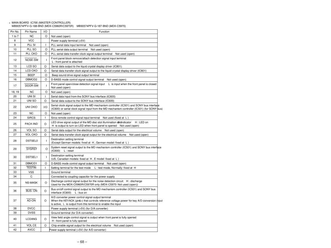
•MAIN BOARD IC700 (MASTER CONTROLLER)
Pin No. | Pin Name | I/O |
|
| Function | |||||
|
|
|
|
|
|
|
|
|
| |
1 to 7 |
| NC | O | Not used (open) |
|
|
|
| ||
8 |
| VCC | — | Power supply terminal (+5V) |
|
|
|
| ||
|
|
|
|
|
|
|
| |||
9 |
| PLL SI | I | PLL serial data input terminal | Not used (open) |
| ||||
|
|
|
|
|
|
|
| |||
10 |
| PLL SO | O | PLL serial data output terminal | Not used (open) |
| ||||
|
|
|
|
|
|
| ||||
11 | PLL CKO | O | PLL serial data transfer clock signal output terminal | Not used (open) | ||||||
|
|
|
|
|
| |||||
12 |
| I | Front panel block remove/attach detection signal input terminal | |||||||
“L”: front panel is attached |
|
|
|
| ||||||
|
|
|
|
|
|
|
|
| ||
|
|
|
|
| ||||||
13 |
| LCD SO | O | Serial data output to the liquid crystal display driver (IC801) | ||||||
14 | LCD CKO | O | Serial data transfer clock signal output to the liquid crystal display driver (IC801) | |||||||
|
|
|
|
|
|
|
| |||
15 |
| BEEP | O | Beep sound drive signal output terminal |
|
|
| |||
|
|
|
|
| ||||||
16 | DBMOD2 | O | Not used (open) | |||||||
|
|
|
|
|
|
| ||||
17 |
| I | Front panel open/close detection signal input | “L” is input when the front panel is closed | ||||||
Not used (open) |
|
|
|
| ||||||
|
|
|
|
|
|
|
|
| ||
|
|
|
|
|
|
|
|
| ||
18, 19 |
| NC | O | Not used (open) |
|
|
|
| ||
20 |
| UNI SI | I | Serial data input from the SONY bus interface (IC600) | ||||||
|
|
|
|
| ||||||
21 |
| UNI SO | O | Serial data output to the SONY bus interface (IC600) | ||||||
|
|
|
|
|
| |||||
22 | UNI CKIO | I/O | Serial clock signal output to the MD mechanism controller (IC501) and SONY bus interface | |||||||
(IC600) or serial clock signal input from the MD mechanism controller (IC501) (for SONY bus) | ||||||||||
|
|
|
|
| ||||||
|
|
|
|
|
|
|
|
| ||
23 |
| NC | O | Not used (open) |
|
|
|
| ||
|
|
|
|
|
| |||||
24 |
| SIRCS | I | Sircs remote control signal input terminal | Not used (fixed at “L”) | |||||
25 | O | LED drive signal output of the MD disc slot illumination and 6 indicator “H”: LED on | ||||||||
“H” is output to turn on LED when front panel is opened Not used (open) | ||||||||||
|
|
|
|
| ||||||
|
|
|
|
|
| |||||
26 |
| VOL SO | O | Serial data output for the electrical volume | Not used (open) | |||||
|
|
|
| |||||||
27 | VOL CKO | O | Serial data transfer clock signal output for the electrical volume Not used (open) | |||||||
|
|
|
|
|
|
|
|
|
| |
28 | DSTSEL0 | I | Destination setting terminal |
|
|
|
| |||
(Except German models: fixed at “H”, German model: fixed at “L”) | ||||||||||
|
|
|
|
| ||||||
|
|
|
|
|
| |||||
29 |
| SYSRST | O | System reset signal output to the MD mechanism controller (IC501) and SONY bus interface | ||||||
| (IC600) “L”: reset |
|
|
|
| |||||
|
|
|
|
|
|
|
|
| ||
|
|
|
|
|
|
|
|
|
| |
30 | DSTSEL1 | I | Destination setting terminal |
|
|
|
| |||
(US, Canadian models: fixed at “H”, E model: fixed at “L”) | ||||||||||
|
|
|
|
| ||||||
|
|
|
|
| ||||||
31 | DBMOD1 | O | Not used (open) | |||||||
|
|
|
|
|
| |||||
32 |
| TESTIN | I | Setting terminal for the test mode “L”: test mode, Normally: fixed at “H” | ||||||
|
|
|
|
|
|
|
|
| ||
33 |
| VSS | — | Ground terminal |
|
|
|
| ||
|
|
|
|
| ||||||
34 |
| C | — | Connected to coupling capacitor for the power supply | ||||||
|
|
|
|
|
| |||||
35 | O | Discharge control signal output for the noise detection circuit “H”: discharge | ||||||||
Used for the | ||||||||||
|
|
|
|
| ||||||
|
|
|
|
|
| |||||
36 |
| BUS- ON | O | Bus on/off control signal output to the MD mechanism controller (IC501) and SONY bus | ||||||
| interface (IC600) “L”: bus on |
|
|
|
| |||||
|
|
|
|
|
|
|
|
| ||
|
|
|
|
|
|
| ||||
|
|
|
|
| A/D converter power control signal output terminal |
| ||||
37 |
| O | When the KEYACK (pin &») that controls reference voltage power for key A/D conversion input | |||||||
|
|
|
|
| is active, “L” is output from this terminal to enable the input | |||||
|
|
|
|
|
| |||||
38 |
| DVCC | — | Power supply terminal (+5V) (for D/A converter) |
| |||||
|
|
|
|
|
|
|
| |||
39 |
| DVSS | — | Ground terminal (for D/A converter) |
|
|
| |||
|
|
|
|
|
| |||||
40 | LCDANG | O | View field angle control signal is output when front panel is fully opened | |||||||
“H”: front panel is fully opened |
|
|
|
| ||||||
|
|
|
|
|
|
|
|
| ||
|
|
|
|
|
| |||||
41 |
| VOL CE | O | Chip enable signal output for the electrical volume | Not used (open) | |||||
42 |
| AVCC | — | Power supply terminal (+5V) (for A/D converter) |
| |||||
– 68 –