Service
Service
Troubleshooting
Troubleshooting consists of performing the “Operator’s Check” on page 12. If the instrument does not perform within limits, return the instrument to Agilent Technologies.
Repair
The only recommended field repair is replacing the outer connector shell for the Option 001 and 003, or replacing the center contact in the 7 mm connector. For any other repair, return the entire instrument to Agilent Technologies.
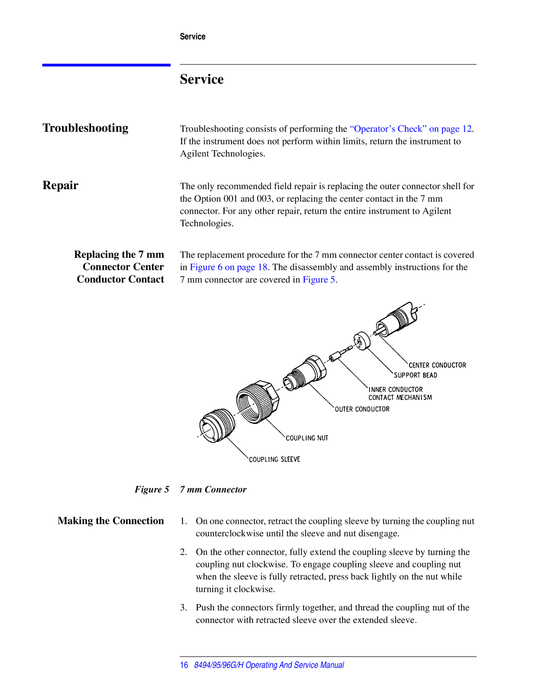
Replacing the 7 mm The replacement procedure for the 7 mm connector center contact is covered Connector Center in Figure 6 on page 18. The disassembly and assembly instructions for the
Conductor Contact 7 mm connector are covered in Figure 5.
Figure 5 7 mm Connector
Making the Connection 1. On one connector, retract the coupling sleeve by turning the coupling nut counterclockwise until the sleeve and nut disengage.
2.On the other connector, fully extend the coupling sleeve by turning the coupling nut clockwise. To engage coupling sleeve and coupling nut when the sleeve is fully retracted, press back lightly on the nut while turning it clockwise.
3.Push the connectors firmly together, and thread the coupling nut of the connector with retracted sleeve over the extended sleeve.
168494/95/96G/H Operating And Service Manual