Specifications
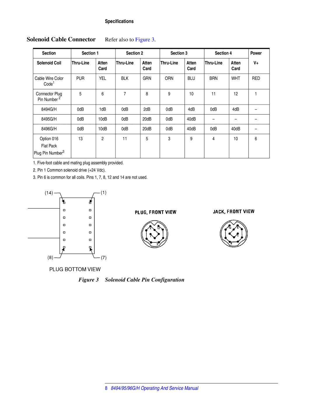
Solenoid Cable Connector | Refer also to Figure 3. |
|
|
|
|
| ||||
|
|
|
|
|
|
|
|
|
|
|
| Section | Section 1 | Section 2 | Section 3 | Section 4 | Power | ||||
|
|
|
|
|
|
|
|
|
|
|
| Solenoid Coil | Atten | Atten | Atten | Atten | V+ | ||||
|
|
| Card |
| Card |
| Card |
| Card |
|
|
|
|
|
|
|
|
|
|
|
|
| Cable Wire Color | PUR | YEL | BLK | GRN | ORN | BLU | BRN | WHT | RED |
| Code1 |
|
|
|
|
|
|
|
|
|
| Connector Plug | 5 | 6 | 7 | 8 | 9 | 10 | 11 | 12 | 1 |
| Pin Number 2 |
|
|
|
|
|
|
|
|
|
| 8494G/H | 0dB | 1dB | 0dB | 2dB | 0dB | 4dB | 0dB | 4dB | – |
|
|
|
|
|
|
|
|
|
|
|
| 8495G/H | 0dB | 10dB | 0dB | 20dB | 0dB | 40dB | – | – | – |
|
|
|
|
|
|
|
|
|
|
|
| 8496G/H | 0dB | 10dB | 0dB | 20dB | 0dB | 40dB | 0dB | 40dB | – |
|
|
|
|
|
|
|
|
|
|
|
| Option 016 | 13 | 2 | 11 | 5 | 3 | 9 | 4 | 10 | 6 |
| Flat Pack |
|
|
|
|
|
|
|
|
|
| Plug Pin Number3 |
|
|
|
|
|
|
|
|
|
1.
2.Pin 1 Common solenoid drive (+24 Vdc).
3.Pin 6 is common for all coils. Pins 1, 7, 8, 12 and 14 are not used.
Figure 3 Solenoid Cable Pin Configuration
88494/95/96G/H Operating And Service Manual
