Overview
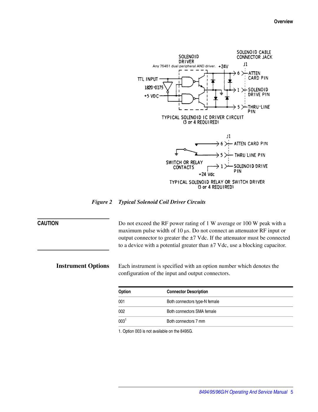
Figure 2 Typical Solenoid Coil Driver Circuits
CAUTION | Do not exceed the RF power rating of 1 W average or 100 W peak with a | ||
|
| maximum pulse width of 10 ∝s. Do not connect an attenuator RF input or | |
|
| output connector to greater the ±7 Vdc. If the attenuator must be connected | |
|
| to a device with a potential greater than ±7 Vdc, use a blocking capacitor. | |
|
|
| |
Instrument Options | Each instrument is specified with an option number which denotes the | ||
|
| configuration of the input and output connectors. | |
|
|
|
|
|
| Option | Connector Description |
|
|
|
|
|
| 001 | Both connectors |
|
|
|
|
|
| 002 | Both connectors SMA female |
|
|
|
|
|
| 0031 | Both connectors 7 mm |
1. Option 003 is not available on the 8495G.
8494/95/96G/H Operating And Service Manual 5