Operating Instructions
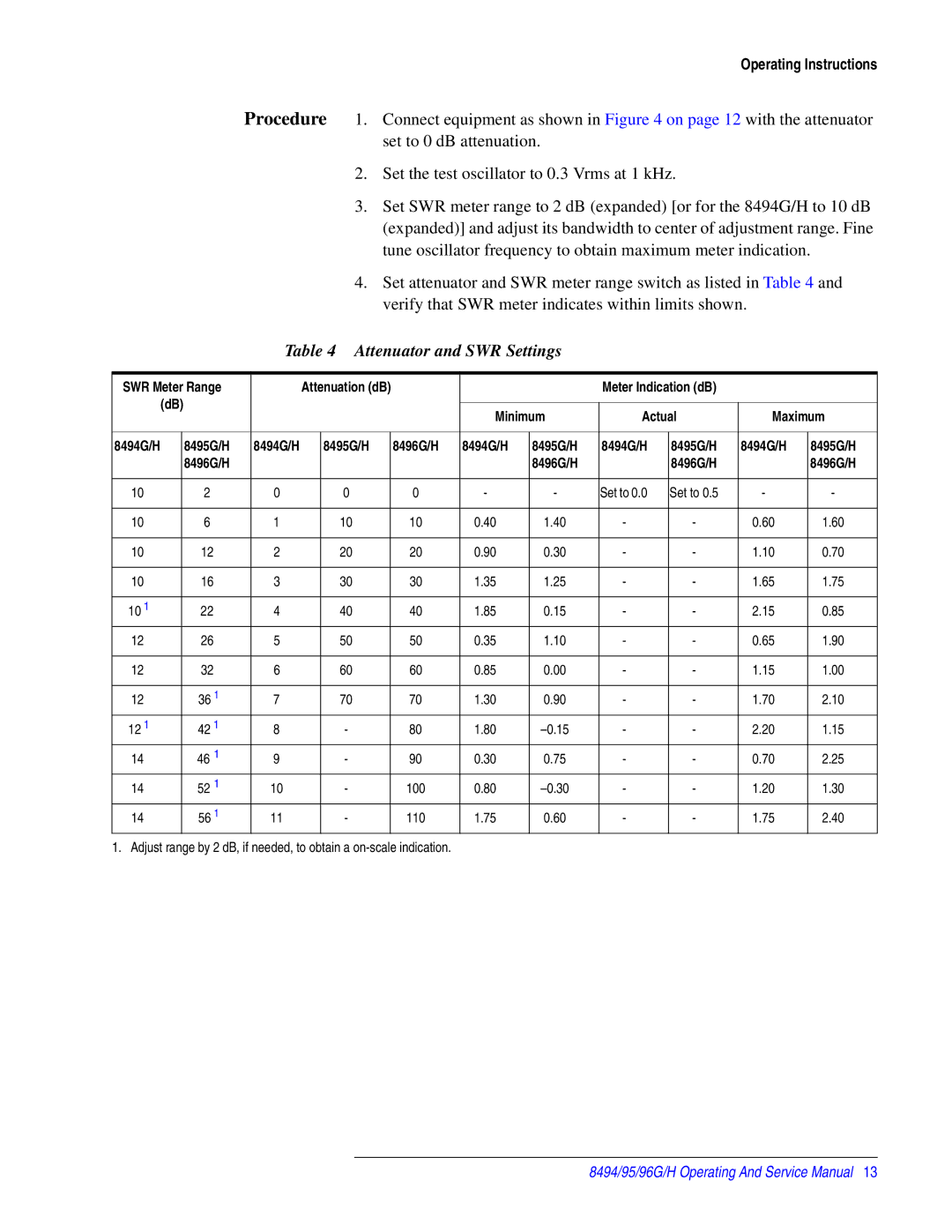
Procedure 1. Connect equipment as shown in Figure 4 on page 12 with the attenuator set to 0 dB attenuation.
2.Set the test oscillator to 0.3 Vrms at 1 kHz.
3.Set SWR meter range to 2 dB (expanded) [or for the 8494G/H to 10 dB (expanded)] and adjust its bandwidth to center of adjustment range. Fine tune oscillator frequency to obtain maximum meter indication.
4.Set attenuator and SWR meter range switch as listed in Table 4 and verify that SWR meter indicates within limits shown.
Table 4 Attenuator and SWR Settings
SWR Meter Range |
| Attenuation (dB) |
|
|
| Meter Indication (dB) |
|
| ||||
| (dB) |
|
|
|
|
|
|
|
|
|
| |
|
|
|
|
| Minimum | Actual | Maximum | |||||
|
|
|
|
|
|
| ||||||
|
|
|
|
|
|
|
|
|
|
|
|
|
8494G/H |
| 8495G/H | 8494G/H |
| 8495G/H | 8496G/H | 8494G/H | 8495G/H | 8494G/H | 8495G/H | 8494G/H | 8495G/H |
|
| 8496G/H |
|
|
|
|
| 8496G/H |
| 8496G/H |
| 8496G/H |
|
|
|
|
|
|
|
|
|
|
|
|
|
10 |
| 2 | 0 |
| 0 | 0 | - | - | Set to 0.0 | Set to 0.5 | - | - |
|
|
|
|
|
|
|
|
|
|
|
|
|
10 |
| 6 | 1 |
| 10 | 10 | 0.40 | 1.40 | - | - | 0.60 | 1.60 |
|
|
|
|
|
|
|
|
|
|
|
|
|
10 |
| 12 | 2 |
| 20 | 20 | 0.90 | 0.30 | - | - | 1.10 | 0.70 |
|
|
|
|
|
|
|
|
|
|
|
|
|
10 |
| 16 | 3 |
| 30 | 30 | 1.35 | 1.25 | - | - | 1.65 | 1.75 |
|
|
|
|
|
|
|
|
|
|
|
|
|
10 1 |
| 22 | 4 |
| 40 | 40 | 1.85 | 0.15 | - | - | 2.15 | 0.85 |
|
|
|
|
|
|
|
|
|
|
|
|
|
12 |
| 26 | 5 |
| 50 | 50 | 0.35 | 1.10 | - | - | 0.65 | 1.90 |
|
|
|
|
|
|
|
|
|
|
|
|
|
12 |
| 32 | 6 |
| 60 | 60 | 0.85 | 0.00 | - | - | 1.15 | 1.00 |
|
|
|
|
|
|
|
|
|
|
|
|
|
12 |
| 36 1 | 7 |
| 70 | 70 | 1.30 | 0.90 | - | - | 1.70 | 2.10 |
|
|
|
|
|
|
|
|
|
|
|
|
|
12 1 |
| 42 1 | 8 |
| - | 80 | 1.80 | - | - | 2.20 | 1.15 | |
14 |
| 46 1 | 9 |
| - | 90 | 0.30 | 0.75 | - | - | 0.70 | 2.25 |
14 |
| 52 1 | 10 |
| - | 100 | 0.80 | - | - | 1.20 | 1.30 | |
|
|
|
|
|
|
|
|
|
|
|
|
|
14 |
| 56 1 | 11 |
| - | 110 | 1.75 | 0.60 | - | - | 1.75 | 2.40 |
1. Adjust range by 2 dB, if needed, to obtain a
8494/95/96G/H Operating And Service Manual 13