Upgrading and Maintaining Components
39
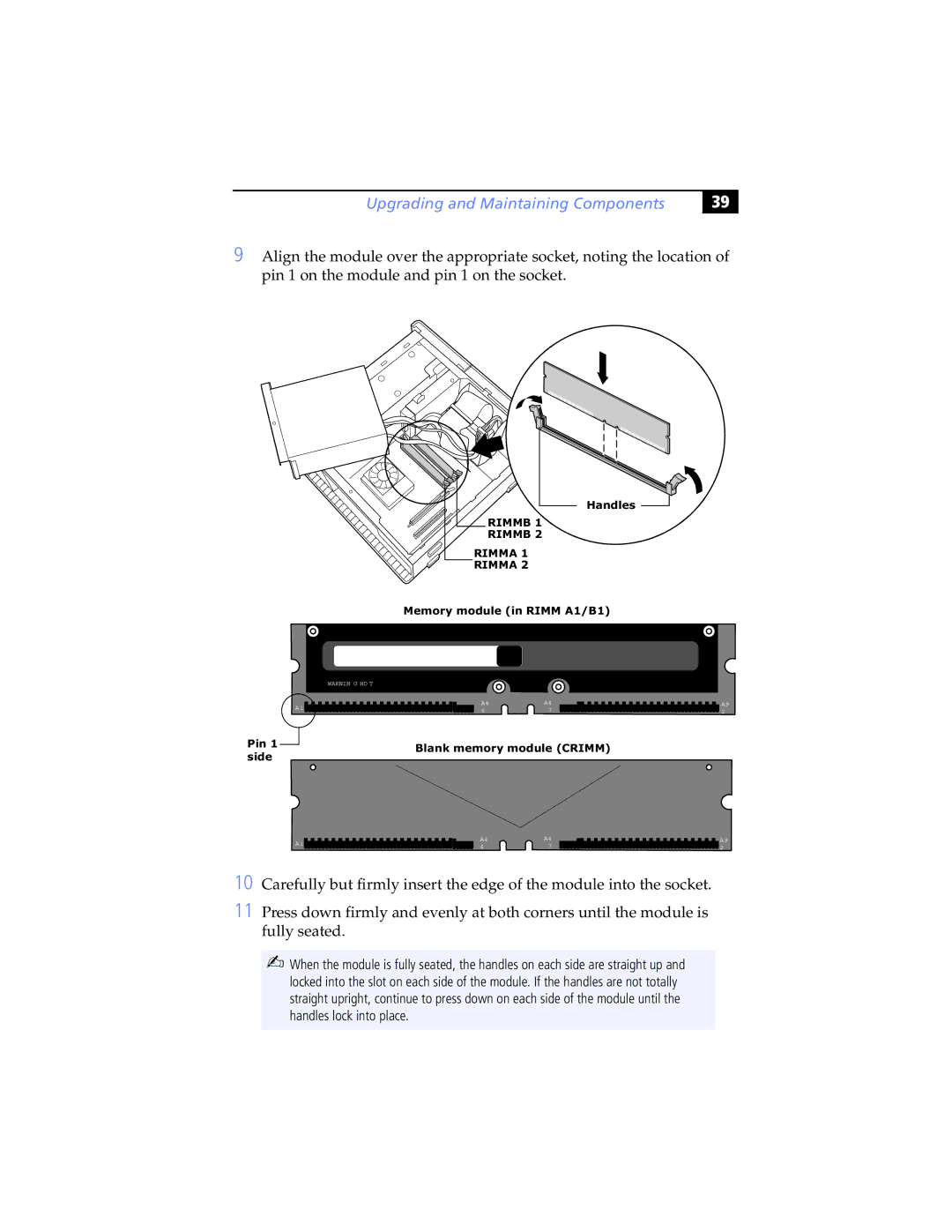
9 Align the module over the appropriate socket, noting the location of pin 1 on the module and pin 1 on the socket.
WARNIN G HO T
A1![]()
![]()
![]()
Pin 1 ![]() side
side
Handles ![]()
RIMMB 1 
RIMMB 2
RIMMA 1
RIMMA 2
Memory module (in RIMM A1/B1)
A4A4
67
Blank memory module (CRIMM)
A9
2
A1 | A4 | A4 | |
6 | 7 | ||
|
A9
2
10 Carefully but firmly insert the edge of the module into the socket.
11 Press down firmly and evenly at both corners until the module is fully seated.
✍When the module is fully seated, the handles on each side are straight up and locked into the slot on each side of the module. If the handles are not totally straight upright, continue to press down on each side of the module until the handles lock into place.
